ฝากข้อความ
หากคุณสนใจในผลิตภัณฑ์ของเราและต้องการทราบรายละเอียดเพิ่มเติม โปรดฝากข้อความไว้ที่นี่ เราจะตอบกลับคุณโดยเร็วที่สุด

The fire truck PTO (Power Take-Off) is a power transmission device that transfers engine power to the fire pump. When the firefighter activates the PTO, mechanical power from the engine is transmitted through the transmission and PTO to the fire pump — this is the core working principle of how a fire fighting truck PTO system operates — enabling the pump to deliver high-pressure, high-flow water or foam without the need for a separate auxiliary engine.
Modern fire trucks typically use side-mounted PTO or full power PTO systems. These offer stable power output, convenient operation, and low maintenance costs, making them an essential component of the fire truck's firefighting system.
 Work")
PTO (Power Take-Off) is a critical component in the fire truck's power system. It is a gear transmission device installed between the engine and the transmission, designed to "divert" a portion of mechanical power from the vehicle's engine or transmission to the fire pump or other auxiliary equipment, without affecting the vehicle's normal driving capability.
The fire truck engine is originally responsible only for driving the wheels. However, once the fire truck arrives at the fire scene, the wheels no longer need power, while the fire pump requires power to draw and pressurize water. The PTO is the device that accomplishes this "power switch."

Power Take-Off (PTO) literally means "power output device."
On a fire truck, it refers to extracting rotational power from the engine flywheel or transmission gears through gear engagement, and delivering it to the fire pump or other auxiliary equipment.
Its name describes its function:
Engine = Power source
PTO = Power distributor
Fire pump = Power consumption end
Therefore, the PTO is the bridge connecting the "power source" and the "firefighting system."
The core reason fire trucks must be equipped with a PTO is that firefighting operations require continuous, stable, high-power output that cannot rely on the vehicle's driving state.
Main reasons:
1. Provides continuous firefighting power
The fire pump needs to run for extended periods during firefighting operations. The PTO allows the engine to continuously drive the fire pump at idle or fixed RPM, ensuring stable water pressure and flow.
2. Improves power utilization efficiency
Without a PTO, a separate auxiliary engine would be required to drive the fire pump, which would increase:
Cost
Maintenance complexity
Risk of failure
Space occupation
The PTO directly utilizes the vehicle's engine power, improving overall efficiency.
3. Supports multiple firefighting systems
Modern industrial fire trucks may include not only water pumps but also:
Foam systems
Dry powder systems
High-pressure water systems
Remote-controlled fire monitors
Without a PTO, there are only two solutions:
Install a separate engine to drive the pump → increases weight, cost, maintenance points, and occupies space
Keep the pump permanently connected to the transmission → pump stops when vehicle stops, unable to pump water on site
The PTO solves both problems at once:
| Mode | PTO Status | Power Destination | Result |
| Driving mode | Disengaged | All to wheels | Normal driving |
| Firefighting mode | Engaged | All to fire pump | Pumping while stationary |
The PTO is essentially a "power distribution and conversion system" that transforms vehicle driving power into firefighting operational power.
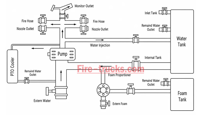
From an engineering perspective, the complete power path is:
Engine → Transmission → PTO → Drive Shaft → Fire Pump → Fire Monitor/Hose System
The PTO's working principle can be summarized in three key stages: power take-off, engagement, and transmission.
The PTO draws power from the engine. Depending on the installation position, the power take-off method differs:
| PTO Type | Installation Position | Power Source | Characteristics |
| Side-mounted PTO | Transmission side | Transmission countershaft gear | Simple structure, lower power (≤50% engine power) |
| Sandwich PTO | Between engine and transmission | Engine flywheel | Full power output, mainstream configuration |
| Split-shaft PTO | Between transmission and driveshaft | Transmission output shaft | High power, allows pumping while driving |
After the driver presses the PTO switch in the cab, the engagement mechanism activates:
| Engagement Method | Working Principle | Common On |
| Electric solenoid control | Electrical signal activates solenoid, pushing shift fork | Mainstream on modern fire trucks |
| Pneumatic control | Compressed air pushes piston, actuating fork | Large fire trucks |
| Manual cable | Mechanical cable directly pulls fork | Older vehicles |
Operation sequence:
Press PTO switch → Solenoid/cylinder actuates → Shift fork pushes sliding gear → Meshes with flywheel or transmission gear → Power connected
After the PTO output shaft begins rotating, power is transmitted through the drive shaft to the fire pump:
PTO output shaft rotates → Drive shaft → Fire pump input shaft → Pump impeller rotates → Water is pressurized and discharged
| Step | Action | Result |
|---|---|---|
| Step 1 | Engine starts, vehicle idling or driving | Engine running, PTO disengaged |
| Step 2 | Arrive at scene, driver presses PTO switch | Driving power disengaged (on some models), PTO gear activated |
| Step 3 | PTO establishes power connection with transmission | Transmission power is diverted to PTO output shaft |
| Step 4 | Drive shaft transmits power to fire pump | Fire pump begins receiving continuous mechanical power |
| Step 5 | Fire pump impeller rotates at high speed | Suction → Pressurization → Delivery to discharge lines → Firefighting |
| Step 6 | System reaches balanced RPM | Stable output, adjustable pressure, flow, and spray pattern |
The fire truck PTO system is a complete power transmission chain, with multiple components working together to transfer engine power to the fire pump. The system can be broken down into six core components:
The engine is the power source of the PTO system and the heart of the entire fire truck.
Function: Generates raw rotational power, driving the flywheel or crankshaft.
Power output: Typically 300–600 HP (depending on chassis model and configuration).
Relationship with PTO: The PTO draws power from the engine flywheel or crankshaft — it is the starting point of power.
Key characteristic: Engine RPM directly affects PTO output speed and the fire pump's water discharge capability. Fire trucks are typically equipped with high-power diesel engines, which not only drive the vehicle but also provide ample power reserve for the fire pump. After PTO engagement, the operator can control pump discharge pressure by adjusting engine RPM.
The transmission is responsible for power delivery and speed matching.
Function: Receives engine power and adjusts speed and torque through different gear combinations.
Relationship with PTO: Side-mounted PTO draws power from internal transmission gears; sandwich PTO is installed at the front of the transmission.
Key characteristic: Transmission gear position does not affect PTO output speed — PTO operates independently of gear selection.
Two power take-off positions:
Transmission side window take-off: PTO mounted on transmission side, drawing power from countershaft or intermediate shaft gears; common on medium-duty fire trucks.
Transmission rear-end take-off (sandwich): PTO installed between engine and transmission, drawing power directly from the flywheel, enabling full power output.
The PTO is the core of the entire system, responsible for "extracting" power from the engine and delivering it to the fire pump.
Function: Extracts power from the engine or transmission and converts it to the speed and torque suitable for the fire pump.
Installation position: Transmission side (side-mounted) or between engine and transmission (sandwich).
Key characteristic: Determines power transmission efficiency, speed matching, and operational convenience.
The drive shaft is the "power bridge" connecting the PTO and the fire pump.
Function: Transmits rotational power from the PTO output shaft to the fire pump input.
Structure: Typically consists of a metal shaft tube, universal joints, and splined connections.
Key characteristic: Must be precisely aligned to avoid vibration; universal joints allow angular compensation.
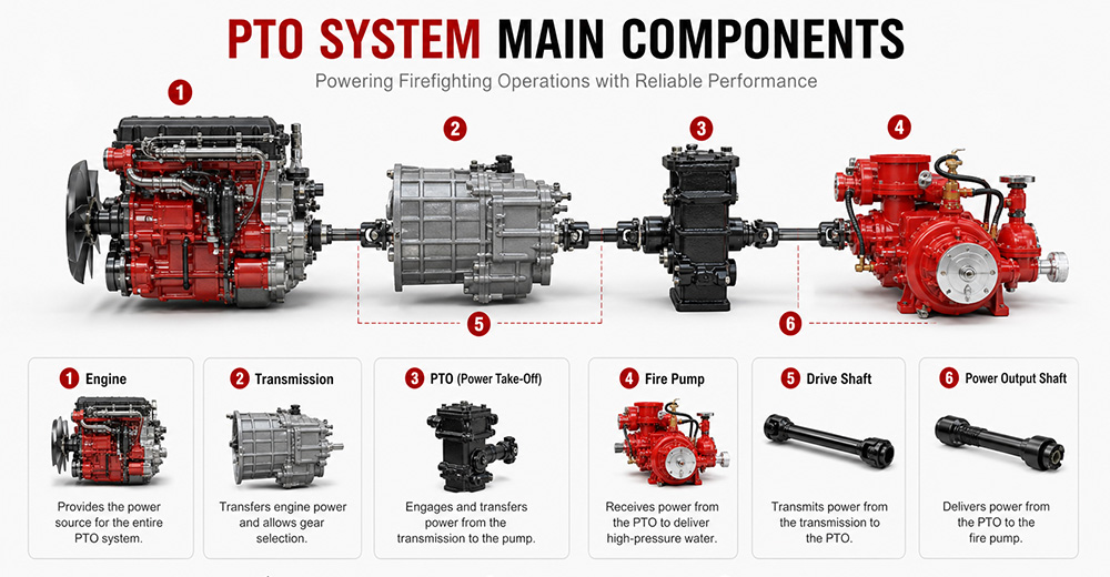
The fire pump is the final load of the PTO system, responsible for converting mechanical energy into water pressure energy.
Function: Receives rotational power from the PTO, drives the impeller to rotate, draws water in, and discharges it under high pressure.
Type: Centrifugal pump (single-stage, two-stage, or multi-stage).
Typical flow rate: 20 L/s – 180 L/s (1,200 – 6,000 L/min).
Typical pressure: 1.0 – 2.5 MPa (10 – 25 bar).
The PTO control system is the "command center" between the driver and the PTO system, responsible for engagement, disengagement, safety protection, and status indication.
Function: Controls PTO engagement and disengagement, monitors system status, and provides safety protection.
Operating location: Cab interior (primary control) and pump panel (auxiliary control).
Control methods: Manual cable, electric solenoid, pneumatic.
Specific control functions:
(1) PTO Engagement Control
The operator presses the PTO switch (electric solenoid/pneumatic) or pulls the lever (manual) in the cab. The control system sends a signal to engage the PTO's internal gears with the power source. After successful engagement is confirmed, an indicator light illuminates, allowing the operator to increase engine RPM.
(2) PTO Disengagement Control
The operator presses the switch again or resets the lever. The control system cuts the signal, and the PTO gears disengage. After disengagement is confirmed, the indicator light turns off.
| PTO Type | Installation Position | Power Source | Power Output | Typical Application |
| Sandwich PTO | Between engine and transmission | Engine flywheel | Full power (≥90%) | Fire pumpers, aerial trucks |
| Split-shaft PTO | Middle of chassis driveshaft | Transmission output shaft | Full power | Large vacuum trucks, airport fire trucks |
| Side-mounted PTO | Transmission side | Transmission gears | Partial power (lower) | Sprinkler trucks, small vacuum trucks |
Sandwich PTO
Advantages: Full power output (≥90%), supports "pumping while driving" (dual-function), high transmission efficiency, easy lubrication.
Disadvantages: Higher cost, complex installation, requires modification to the engine-transmission connection.
Split-shaft PTO
Advantages: Full power output, no additional space required, high reliability, good dynamic balance, can replace auxiliary engine to drive large pumps.
Disadvantages: Requires cutting the original driveshaft, installation position selection must consider driveshaft angle and length compensation.
Side-mounted PTO
Advantages: Low cost, simple installation, can draw power directly from the transmission side.
Disadvantages: Only partial power available, lower output torque, cannot drive high-power fire pumps, mainly used for low-speed, low-power equipment.
 for Fire Trucks")
The process follows a clear mechanical transmission chain:
Engine → PTO → Drive Shaft → Fire Pump → Impeller Rotation → Suction → Pressurization → Fire Monitor
| Factor | Role |
|---|---|
| Centrifugal pump characteristic | When impeller speed is constant, discharge pressure remains naturally stable |
| PTO rigid connection | No slippage or power loss, ensuring continuous stable power input |
| Pressure governor | Automatically detects flow changes and adjusts engine RPM to maintain set pressure |
| Relief valve | Automatically bypasses when pressure exceeds limit, preventing equipment damage |
① Pump speed is determined by engine RPM
Fire pump impeller speed = Engine RPM × PTO ratio. The PTO ratio is fixed (e.g., 1.75:1), so pump speed changes directly with engine RPM.
Calculation formula:
Engine RPM × PTO ratio = Pump speed (RPM)
② Physical relationship between pressure and speed
The pressure generated by a centrifugal pump is proportional to the square of the impeller speed. This physical law means that small changes in RPM cause significant pressure fluctuations.
Speed increases → Centrifugal force increases → Discharge pressure rises
Speed decreases → Centrifugal force decreases → Discharge pressure drops

1. PTO will not engage
Possible causes: Low air pressure (pneumatic type), faulty solenoid, damaged or stuck cable, interlock conditions not met (parking brake not applied, transmission not in neutral).
Solutions: Check air system pressure (must be ≥0.6 MPa); test solenoid; inspect cable; confirm parking brake is applied and transmission is in neutral.
2. PTO engages but pump does not work
Possible causes: PTO clutch failure, broken drive shaft or worn splines, damaged internal gears.
Solutions: Check PTO clutch engagement; inspect drive shaft for breakage or loose connections; disassemble and inspect internal gears.
3. PTO unusual noise
Possible causes: Poor gear meshing or wear, worn bearings, insufficient or degraded lubrication, PTO not fully disengaged.
Solutions: Check gear clearance and tooth wear; inspect bearings; replace with qualified lubricant; confirm PTO is fully disengaged.
4. PTO oil leakage
Possible causes: Worn or deteriorated seals, cracked housing, loose mounting bolts.
Solutions: Replace seals (O-rings, oil seals); inspect housing for cracks; tighten mounting bolts.
5. PTO overheating
Possible causes: Prolonged high-load operation, insufficient or degraded lubricating oil, cooling system failure.
Solutions: Reduce load or shut down for cooling; replace with qualified lubricant; inspect cooling lines.
6. PTO insufficient power
Possible causes: Improper PTO ratio selection, engine RPM set too low, clutch slippage.
Solutions: Confirm PTO ratio matches the fire pump; increase engine RPM to rated operating range; inspect clutch for slippage.
Q1. What does PTO stand for on a fire truck?
PTO stands for Power Take-Off. It is a mechanical system that transfers engine power from the truck's transmission to the fire pump. In simple terms, PTO allows the fire truck's engine to power the pumping system so it can deliver high-pressure water or foam for firefighting operations without needing a separate engine. It is a critical component in industrial and municipal fire trucks.
Q2. Why do fire trucks need a PTO?
Fire trucks need a PTO because it enables the vehicle's main engine to drive the fire pump efficiently. Without a PTO, the fire pump would require a separate engine, which increases cost, weight, and maintenance complexity. PTO systems provide a compact, reliable, and fuel-efficient way to ensure continuous water or foam supply during firefighting operations.
Q3. Can a fire truck operate without a PTO?
Most modern fire trucks cannot operate their pumping system without a PTO because the PTO is responsible for transferring engine power to the fire pump. However, some specialized fire vehicles may use an independent auxiliary engine to drive the pump. These designs are less common due to higher cost, increased maintenance, and lower efficiency compared to PTO-based systems.
Q4. What is the difference between PTO and a fire pump?
The PTO is a power transmission device, while the fire pump is a water or foam pumping system. The PTO delivers mechanical power from the engine to the pump, and the fire pump converts that power into hydraulic pressure to move water or foam. In short, PTO is the "power source connector," and the fire pump is the "firefighting output device."
Q5. How much power can a fire truck PTO provide?
The power output of a fire truck PTO depends on the vehicle design and transmission system. Typically, PTO systems can provide between 50 kW to over 300 kW of mechanical power. Heavy-duty industrial and airport fire trucks often use high-capacity PTO systems capable of supporting large-flow fire pumps and continuous high-pressure operations.
Q6. What are the different types of fire truck PTOs?
There are several types of fire truck PTO systems, including side-mounted PTO, rear-mounted PTO, split shaft PTO, and full power PTO. Side-mounted PTO is commonly used in standard fire trucks, while split shaft and full power PTO systems are used in industrial and airport fire trucks where higher power output and continuous operation are required.
Q7. How do you maintain a fire truck PTO?
PTO maintenance includes regular inspection of lubrication oil levels, checking for leaks, tightening mounting bolts, and ensuring proper alignment of the drive shaft. Operators should also test engagement and disengagement functions regularly. Preventive maintenance is essential to avoid overheating, mechanical wear, and unexpected failure during emergency operations.
Q8. What causes a fire truck PTO to fail?
Common causes of PTO failure include insufficient lubrication, worn gears, misalignment of the drive shaft, overheating, and improper operation by the driver. Electrical or hydraulic control system failures can also prevent PTO engagement. Regular maintenance and correct operating procedures significantly reduce the risk of PTO failure.
Q9. Which PTO is best for industrial fire trucks?
For industrial fire trucks, the best option is usually a split shaft PTO or full power PTO system. These systems can handle high power output, continuous operation, and large-capacity fire pumps. They are widely used in petrochemical plants, refineries, airports, and large industrial facilities where reliable and long-duration firefighting performance is required.
Q10. What should buyers consider when choosing a fire truck PTO?
Buyers should consider engine power compatibility, required fire pump flow rate, vehicle type, and working environment. It is also important to evaluate PTO durability, cooling performance, maintenance accessibility, and compatibility with the chassis. For export projects, compliance with international standards and local regulations should also be taken into account to ensure approval and operational reliability.
PTO (Power Take-Off) is the core system that transfers engine power to the fire pump — it determines whether the entire firefighting system can operate properly.
The fire truck power chain is: Engine → Transmission → PTO → Drive Shaft → Fire Pump → Fire Monitor. Any weak link in this chain affects final firefighting performance.
The primary function of the PTO is to provide stable, continuous mechanical power output, enabling the fire truck to deliver efficient water or foam supply without requiring a separate engine.
Different PTO types (Side-mounted, Rear-mounted, Split shaft, Full power) are suited to different fire truck classes. Industrial fire trucks typically prioritize high-power PTO systems.
PTO performance must match the fire pump flow rate and vehicle chassis, otherwise issues such as insufficient power, unstable pressure, or system overload may occur.
Regular PTO system maintenance (lubrication, tightening, alignment inspection) is key to ensuring reliable fire truck operation, especially in high-intensity industrial applications.
When purchasing industrial fire trucks, buyers should not focus solely on price. PTO power, stability, compatibility, and after-sales support are equally critical factors to evaluate.
For high-risk scenarios such as petrochemical plants, airports, and large industrial parks, Full Power PTO or Split Shaft PTO systems are recommended to ensure continuous operational capability.


คุณอาจสนใจข้อมูลต่อไปนี้
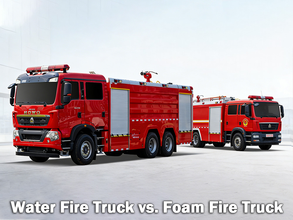
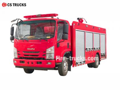
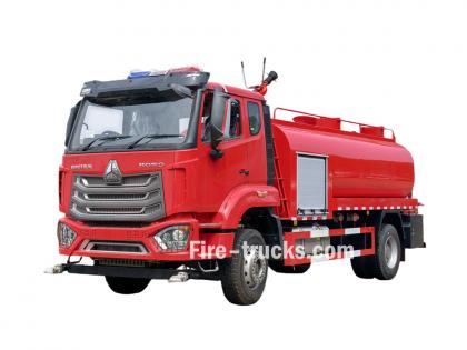
รถดับเพลิงน้ำ รถดับเพลิงแบบใช้โฟมใช้ดับเพลิงทั่วไปที่ลุกไหม้จากไม้ กระดาษ และผ้า ส่วนรถดับเพลิงแบบใช้โฟมใช้ดับเพลิงที่ลุกไหม้จากของเหลวไวไฟ เช่น น้ำมันเบนซินและน้ำมันเครื่อง การเลือกใช้แบบใดนั้นขึ้นอยู่กับอันตรายที่เกิดขึ้น เอ รถดับเพลิงน้ำ รถดับเพลิงประเภทนี้มีถังน้ำขนาดใหญ่และใช้ปั๊มแรงดันสูงในการส่งน้ำผ่านสายยางหรือปืนฉีดน้ำบนตัวรถ เป็นรถดับเพลิงชนิดที่พบได้บ่อยที่สุดในหน่วยดับเพลิงของเทศบาลและโรงงานอุตสาหกรรมทั่วโลก เอ รถดับเพลิงโฟม ในทางกลับกัน รถบรรทุกน้ำถูกออกแบบมาเป็นพิเศษเพื่อขนส่งและส่งโฟมดับเพลิง เมื่อน้ำเพียงอย่างเดียวไม่สามารถดับไฟได้อย่างมีประสิทธิภาพ เช่น ไฟที่เกิดจากของเหลวไวไฟ สารเคมี หรือเชื้อเพลิง โฟมจึงเป็นตัวเลือกที่ดีกว่า โฟมทำงานโดยการสร้างชั้นปกคลุมเหนือไฟ ตัดออกซิเจนและป้องกันการลุกไหม้ซ้ำ I. รถดับเพลิงแบบใช้น้ำคืออะไร? รถดับเพลิงที่ใช้น้ำเป็นพาหนะก็คือรถที่ติดตั้งถังเก็บน้ำขนาดใหญ่ ปั๊มน้ำกำลังสูง และสายยางหรือหัวฉีดสำหรับส่งน้ำไปดับไฟ โดยทั่วไปถังเก็บน้ำจะมีขนาดความจุระหว่าง 500 ถึง 3,000 แกลลอน (ประมาณ 2,000 ถึง 12,000 ลิตร) ปั๊มจะสูบน้ำจากถังหรือจากแหล่งภายนอก เช่น หัวจ่ายน้ำดับเพลิง ทะเลสาบ หรือบ่อ แล้วดันน้ำผ่านสายยางด้วยแรงดันสูง รถดับเพลิงแบบใช้น้ำมีประสิทธิภาพดีที่สุดในพื้นที่ใดบ้าง: รถดับเพลิงแบบใช้น้ำเหมาะสำหรับ... ไฟไหม้ระดับ A ซึ่งเกี่ยวข้องกับเชื้อเพลิงทั่วไป: ไม้และวัสดุไม้ กระดาษและกระดาษแข็ง ผ้าและสิ่งทอ ยางและพลาสติก หญ้า พุ่มไม้ และวัสดุจากป่า หากไฟไหม้เกี่ยวข้องกับวัสดุที่ติดไฟได้ในบ้าน โกดัง หรือทุ่งนา โดยทั่วไปแล้วน้ำจะสามารถดับไฟได้ ข้อจำกัดของน้ำ: น้ำมีจุดอ่อนสำคัญอย่างหนึ่ง คือ เมื่อฉีดพ่นลงบนของเหลวที่กำลังลุกไหม้ เช่น น้ำมันเบนซิน น้ำมันเครื่อง หรือสารเคมี น้ำจะจมลงเพราะหนักกว่าเชื้อเพลิงเหล่านั้น เชื้อเพลิงจะลอยอยู่ด้านบนและลุกไหม้ต่อไป ในบางกรณี น้ำอาจทำให้ไฟลุกลามไปยังพื้นที่กว้างขึ้นด้วย นั่นเป็นเหตุผลว่าทำไมน้ำเพียงอย่างเดียวจึงไม่สามารถดับไฟที่เกิดจากของเหลวไวไฟได้ ข้อมูลจำเพาะของปั๊มดับเพลิงสำหรับรถดับเพลิง: รถดับเพลิงน้ำ เครื่องตรวจสอบเพลิงไหม้ ข้อมูลจำเพาะ: II. รถดับเพลิงโฟมคืออะไร? รถดับเพลิงโฟมเป็นยานพาหนะเฉพาะทางที่ออกแบบมาเพื่อขนส่งและส่งโฟมดับเพลิง โดยมีถังแยกสองถัง คือ ถังน้ำและถังบรรจุสารเข้มข้นสำหรับทำโฟม ระบบผสมโฟมจะผสมน้ำและสารเข้มข้นในอัตราส่วนที่กำหนด โดยทั่วไปคือ 1%, 3% หรือ 6% ของสารเข้มข้นต่อน้ำ จากนั้นส่วนผสมนี้จะผ่านหัวฉีดโฟมและมีการเติมอากาศเข้าไป ทำให้เกิดโฟมที่ขยายตัวและคงตัว โฟมทำงานอย่างไร: ฟองจะก่อตัวเป็นชั้นปกคลุมของเหลวหรือวัสดุที่กำลังไหม้ ผ้าห่มนี้: ตัดการจ่ายออกซิเจนให้กับไฟ ช่วยลดอุณหภูมิพื้นผิวเชื้อเพลิง ป้องกันไม่ให้ไอระเหยที่ติดไฟได้เล็ดลอดออกมา ป้องกันไม่ให้ไฟลุกไหม้ขึ้นอีก รถดับเพลิงแบบใช้โฟมทำงานได้ดีที่สุดในที่ใดบ้าง: รถดับเพลิงชนิดใช้โฟมเป็นสิ่งจำเป็นสำหรับ ไฟไหม้ประเภท B ซึ่งเกี่ยวข้องกับของเหลวไวไฟและติดไฟได้: น้ำมันเบนซินและดีเซล น้ำมันเชื้อเพลิงเครื่องบินและน้ำมันก๊าด น้ำมันและจาระบี แอลกอฮอล์และเอทานอล สารเคมีอุตสาหกรรม โฟมยังมีประสิทธิภาพในการดับเพลิงประเภท A บางประเภทที่น้ำเปล่าไม่สามารถควบคุมได้ เช่น ไฟไหม้ในโกดังที่มีสินค้าวางซ้อนกัน หรือโรงเก็บยางรถยนต์ การใช้งานทั่วไป: แอปพลิเคชัน เหตุผลที่โฟมได้ผล สนามบิน ไฟไหม้น้ำมันเชื้อเพลิงเครื่องบินต้องใช้โฟมดับเพลิง น้ำใช้ไม่ได้ผล โรงกลั่นน้ำมัน มีของเหลวไวไฟปริมาณมากอยู่ในบริเวณนั้น โรงงานเคมี สารเ...
รายละเอียด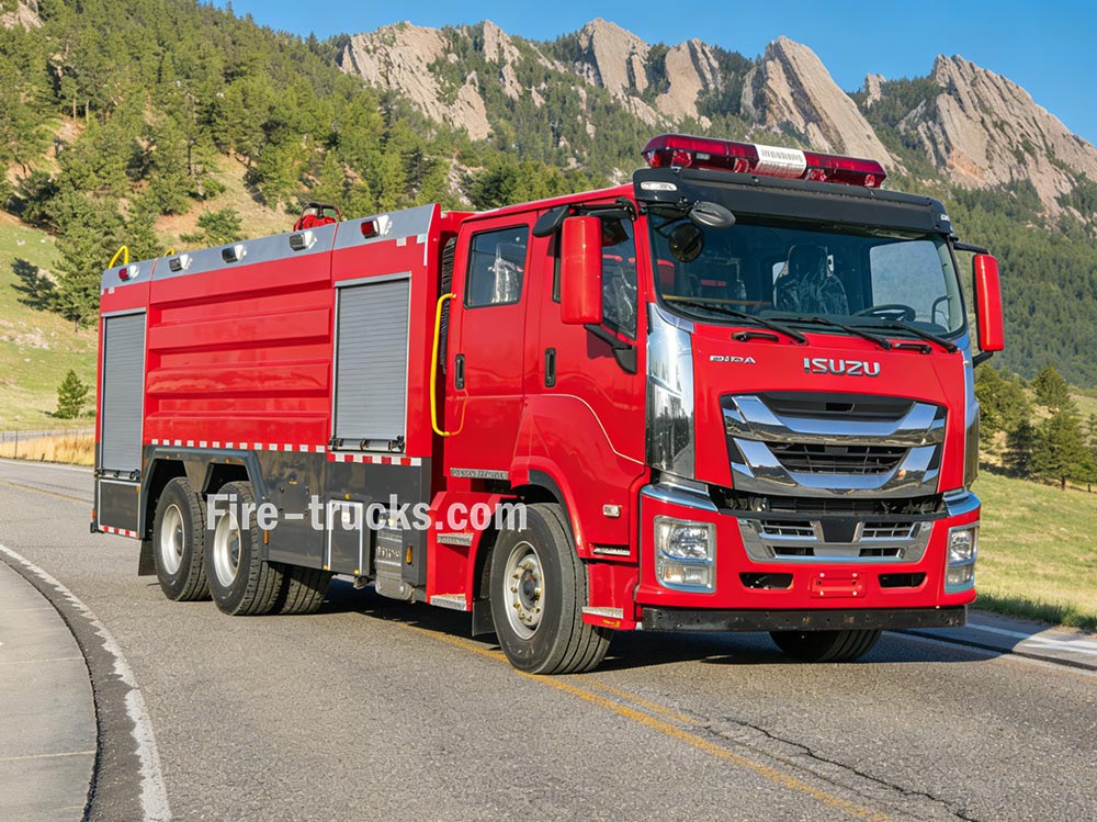
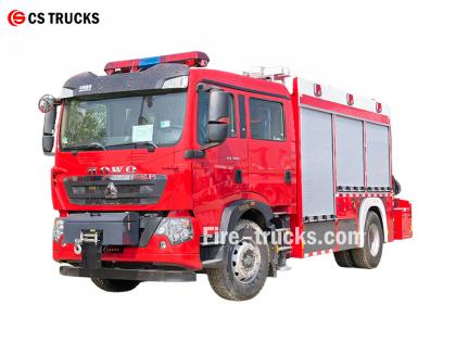
รถดับเพลิง การทำงานของระบบต่างๆ นั้นประสานกันเพื่อให้ได้มาซึ่งการจ่ายน้ำ การสร้างแรงดัน และการดับเพลิง การเข้าใจหลักการเหล่านี้จะช่วยให้เจ้าหน้าที่ดับเพลิงปฏิบัติงานได้อย่างมีประสิทธิภาพในสถานการณ์ฉุกเฉิน » Ⅰ. วิธีการทำงานของรถดับเพลิง : ▪ ก. ระบบปั๊ม: หัวใจสำคัญของการดับเพลิง: หัวใจสำคัญของรถดับเพลิงทุกคันคือปั๊มน้ำ อุปกรณ์กำลังสูงนี้จะดูดน้ำจากถังเก็บน้ำภายในรถหรือจากแหล่งภายนอก เช่น หัวจ่ายน้ำดับเพลิง ทะเลสาบ หรือสระน้ำ และส่งน้ำผ่านสายยางด้วยแรงดันสูง ปั๊มที่ใช้กันทั่วไปมากที่สุดคือปั๊มแบบแรงเหวี่ยง ซึ่งอาศัยใบพัดหมุนเพื่อเพิ่มแรงดันและเคลื่อนย้ายน้ำ เจ้าหน้าที่ดับเพลิงควบคุมการไหลของน้ำโดยใช้คันโยกและมาตรวัดต่างๆ บนแผงควบคุมปั๊ม พวกเขาสามารถปรับแรงดันได้ตามต้องการและส่งน้ำไปยังสายฉีดน้ำหลายสายพร้อมกันได้ ประเภทปั๊ม ลักษณะเฉพาะ แอปพลิเคชันที่ดีที่สุด ปั๊มแรงเหวี่ยงแบบขั้นตอนเดียว อัตราการไหลสูง แรงดันปานกลาง การดับเพลิงทั่วไปของเทศบาล ปั๊มแรงเหวี่ยงสองขั้นตอน สามารถสลับระหว่างปริมาตรและความดันได้ อาคารสูงระฟ้าและสายยางยาววางอยู่ ปั๊มหลายขั้นตอน ความดันสูงมาก โรงงานอุตสาหกรรม ระบบโฟม ▪ พารามิเตอร์สำคัญของปั๊ม: › อัตราการไหล: 1,200 - 6,000 ลิตรต่อนาที (ขึ้นอยู่กับรุ่น) › แรงดันสูงสุด: 1.0 - 2.5 MPa (10-25 บาร์) › เวลาในการเตรียมพร้อมใช้งาน: ≤30 วินาที ▪ ข. ถังเก็บน้ำและระบบจัดเก็บน้ำ: › ความจุถังน้ำมัน: 500 - 1,500 แกลลอน (ประมาณ 2,000 ถึง 6,000 ลิตร) ขึ้นอยู่กับขนาดและประเภทของรถ › วัสดุของถัง: เหล็กกล้าไร้สนิมทนการกัดกร่อน หรือเหล็กกล้าคาร์บอนเคลือบผิว › แผ่นกั้นภายใน: ช่องแบ่งหลายช่องพร้อมการออกแบบป้องกันน้ำกระชากเพื่อควบคุมการเคลื่อนที่ของน้ำในระหว่างการรับมือเหตุฉุกเฉิน › ระยะเวลาเติมน้ำ: ≤3 นาที ผ่านทางหัวจ่ายน้ำดับเพลิงหรือการสูบน้ำ › ตัวบ่งชี้ระดับน้ำ: มาตรวัดแบบมองเห็นได้ที่ด้านข้างถัง; จอแสดงผลในห้องโดยสาร (เลือกได้) ถังน้ำถูกสร้างขึ้นจากวัสดุที่ทนต่อการกัดกร่อน โดยทั่วไปคือเหล็กกล้าไร้สนิมหรือเหล็กกล้าคาร์บอนเคลือบผิว พร้อมแผ่นกั้นภายในที่ช่วยควบคุมแรงดันน้ำในระหว่างการขับขี่เพื่อตอบสนองต่อเหตุฉุกเฉิน ▪ ค. ระบบสายยางและหัวฉีด รถดับเพลิงมีสายยางหลายประเภทที่มีหน้าที่แตกต่างกัน: › สายฉีดน้ำดับเพลิง: เส้นผ่านศูนย์กลาง 1.5 - 2.5 นิ้ว — ส่งน้ำไปยังแหล่งกำเนิดไฟโดยตรง › สายส่งน้ำ: เส้นผ่านศูนย์กลาง 4-5 นิ้ว — ใช้สำหรับลำเลียงน้ำจากหัวจ่ายน้ำดับเพลิงหรือเครื่องสูบน้ำอื่นๆ › สายฉีดน้ำแรงดันสูง: ขนาดเล็ก ม้วนเก็บได้ — ใช้สำหรับดับเพลิงขนาดเล็ก เช่น ไฟไหม้หญ้าหรือรถยนต์ หัวฉีดที่ปลายสายยางช่วยให้เจ้าหน้าที่ดับเพลิงสามารถควบคุมกระแสน้ำ ปรับแรงดัน รูปแบบ และทิศทางตามประเภทของไฟได้ ▪ D. เครื่องตรวจสอบเพลิงไหม้ › เครื่องฉีดน้ำดับเพลิง: ส่งกระแสน้ำปริมาณมากเพื่อดับเพลิงในพื้นที่ขนาดใหญ่ สามารถติดตั้งอยู่กับที่หรือควบคุมจากระยะไกลได้ › เครื่องพ่นผงเคมีแห้ง: พ่นผงเคมีแห้งเพื่อดับเพลิงที่เกิดจากของเหลวไวไฟ ก๊าซ และไฟฟ้าลัดวงจร › จอภาพแบบผสม: สามารถจ่ายได้ทั้งน้ำและผงแห้ง สลับระหว่างสื่อได้ตามต้องการ ▪ E. ระบบควบคุมเครื่องยนต์ ระบบส่งกำลัง และปั๊ม เครื่องยนต์และระบบส่งกำลัง ● กำลังเครื่องยนต์: 300 - 600 แรงม้า — ให้พลังงานทั้งในการขับเคลื่อนยานพาหนะและระบบดับเพลิง ● ประเภทเครื่องยนต์: เครื่องยนต์ดีเซลขนาดใหญ่ — รับประกันประสิทธิภาพที่เชื่อถือได้ทั้งบนถนนในเมืองหรือภูมิประเทศขรุขระภายใต้ภาระเต็มที่ ● ระบบส่งกำลังแบบเพลาส่งกำลัง (PTO): ทำหน้าที่ส่งกำลังจ...
รายละเอียด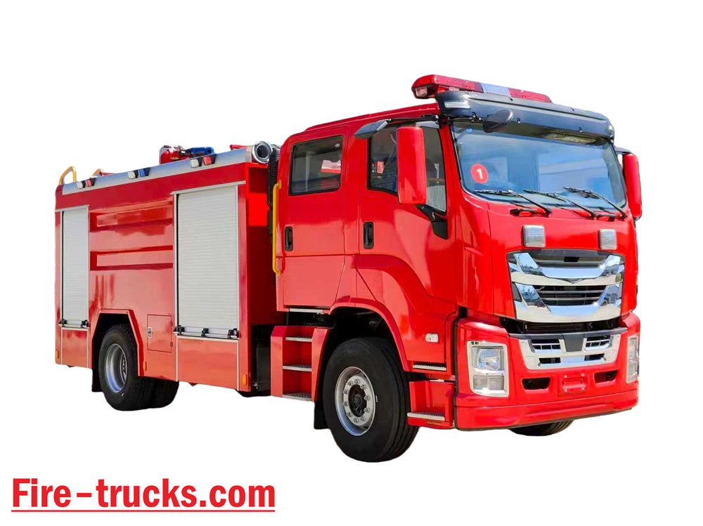
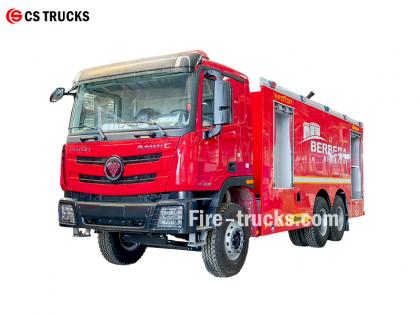
ในฐานะโรงงานผลิตรถดับเพลิงอีซูซุที่เชี่ยวชาญที่สุด หัวใจหลักของการออกแบบรถดับเพลิงอีซูซุ NPR คือการผสานระบบดับเพลิงด้วยโฟมเข้ากับรถบรรทุกน้ำดับเพลิง ทำให้เกิดอุปกรณ์ดับเพลิงแบบผสมผสานที่สามารถฉีดพ่นได้ทั้งน้ำและโฟม สามารถดับไฟได้ด้วยตัวเอง ส่งน้ำหรือโฟมผสมไปยังอุปกรณ์อื่นๆ และเหมาะสำหรับการใช้งานในพื้นที่แห้งแล้งและขาดแคลนน้ำ ★ ด้านเทคนิค ข้อกำหนด รถดับเพลิงทุกคันจาก CS Trucks ผลิตตามความต้องการของลูกค้า 100% ความจุ รุ่นเครื่องยนต์ น้ำ โฟม ปั๊มดับเพลิง เครื่องตรวจสอบเพลิงไหม้ 2,500 ลิตร อิซูซู 4HK1 / 19 0 แรงม้า 2,500 ลิตร 500 ลิตร ปั๊มดับเพลิง CB10/40 PL8/32 รถบรรทุกหัวลากดับเพลิง ISUZU รุ่นปี 2026 อย่างเป็นทางการ ภาพวาดโครงรถดับเพลิงต้นฉบับปี 2026 รายการ รายละเอียดการออกแบบรถดับเพลิงอีซูซุ แกนหลักของการออกแบบ ผสานระบบดับเพลิงแบบโฟมเข้ากับรถดับเพลิงบรรทุกน้ำ ทำให้ได้รถดับเพลิงอเนกประสงค์ที่สามารถพ่นได้ทั้งน้ำและโฟม คุณสมบัติเด่น ได้แก่: • ระบบดับเพลิงแบบอิสระ • การจ่ายน้ำหรือส่วนผสมโฟมไปยังอุปกรณ์อื่นๆ • เหมาะสำหรับพื้นที่แห้งแล้งหรือพื้นที่ขาดแคลนน้ำ ทำให้สามารถใช้งานได้หลากหลายวัตถุประสงค์ แนวคิดการออกแบบโดยรวม ออกแบบมาเพื่อตอบสนองความต้องการด้านการดับเพลิงในโรงงานและพื้นที่โดยรอบ ด้วยความสามารถที่เพิ่มขึ้นในการดับเพลิงน้ำมัน ไฟฟ้า และวัสดุแข็ง ตัวรถประกอบด้วยโครงตัวถังและอุปกรณ์ตัวถังเฉพาะทาง เน้นความน่าเชื่อถือ การใช้งานหลากหลาย และใช้งานง่าย การเลือกแชสซี • ใช้แชสซีประเภท II ที่ได้รับการพิสูจน์แล้วว่าทนทานต่อการใช้งานปานกลางหรือหนัก • แนะนำให้ใช้ระบบขับเคลื่อนสี่ล้อเพื่อเพิ่มความคล่องตัวและการยึดเกาะในภูมิประเทศที่ซับซ้อน รถดับเพลิงน้ำรุ่นใหม่ Isuzu 700P ปี 2026 ดีไซน์ใหม่ ส่วนประกอบหลักของระบบและประเด็นสำคัญในการออกแบบ 1. ถังเก็บน้ำและถังเก็บน้ำยาโฟม • วัสดุ: สแตนเลสสตีล ทนทานต่อการกัดกร่อน • ความจุที่แนะนำ: ถังน้ำ 3000–5000 ลิตร, ถังบรรจุน้ำยาโฟม 300–600 ลิตร • การปรับโครงสร้างให้เหมาะสม: แผ่นกั้นภายในแยกห้องน้ำและห้องโฟม สามารถสลับไปใช้โหมดถังน้ำเดี่ยวได้ผ่านพอร์ตเชื่อมต่อ ทำให้สามารถใช้งานได้หลากหลายวัตถุประสงค์ 2. ระบบผสมโฟม • ใช้เครื่องควบคุมสัดส่วนแรงดันสมดุล (ส่วนประกอบหลัก) เพื่อผสมน้ำและสารเข้มข้นสำหรับทำโฟมในอัตราส่วน 3% หรือ 6% อย่างแม่นยำ • ให้ผลลัพธ์ที่เสถียร ไม่ได้รับผลกระทบจากความผันผวนของอัตราการไหลหรือความดัน เหมาะสำหรับผู้ใช้งานทั่วไปที่ไม่ใช่ผู้เชี่ยวชาญ • มีช่องดูดโฟมภายนอกสำหรับเติมโฟม ณ จุดใช้งาน 3. ระบบระบายน้ำ • ปั๊มดับเพลิง: ปั๊มแรงเหวี่ยงหลายขั้นตอนประสิทธิภาพสูง ประหยัดพลังงาน อัตราการไหล ≥ 4 0 แอล/เอส • เครื่องฉีดน้ำดับเพลิง: เครื่องฉีดน้ำ/โฟมแบบควบคุมระยะไกล ใช้งานได้สองวัตถุประสงค์ ระยะการใช้งาน ≥50 เมตร ปรับมุมได้ • รองรับการเชื่อมต่อกับสายดับเพลิงและหัวฉีดโฟมเพื่อการใช้งานที่ยืดหยุ่น รถดับเพลิงโฟม ISUZU NPR ดีไซน์ใหม่ ปี 2026 กรณีการใช้งานและข้อดี ไฟไหม้จากคราบน้ำมันในโรงงาน เหมาะสมอย่างยิ่ง; โฟมสามารถดับไฟได้อย่างรวดเร็วโดยการตัดออกซิเจน เหตุเพลิงไหม้อุปกรณ์ไฟฟ้าเบื้องต้น สามารถใช้โฟมหรือผงแห้งผสมกันได้ (ต้องตรวจสอบให้แน่ใจว่าฉนวนไฟฟ้ามีความปลอดภัย) การเผาไหม้ของวัสดุแข็ง เครื่องฉีดน้ำดับเพลิงสามารถดับไฟได้โดยตรงและมีประสิทธิภาพ การปฏิบัติงานในสภาพแวดล้อมที่ขาดแคลนน้ำ สามารถใช้เป็นยานพาหนะสนับสนุนการจัดหาน้ำ ช่วยให้สามารถขนส่งน้ำในระยะทางไกลได้ รถดับเพลิง Isuzu 4X2 FVR สำหรับประเทศฟิลิปปินส์ ความจุของน้ำ 20...
รายละเอียด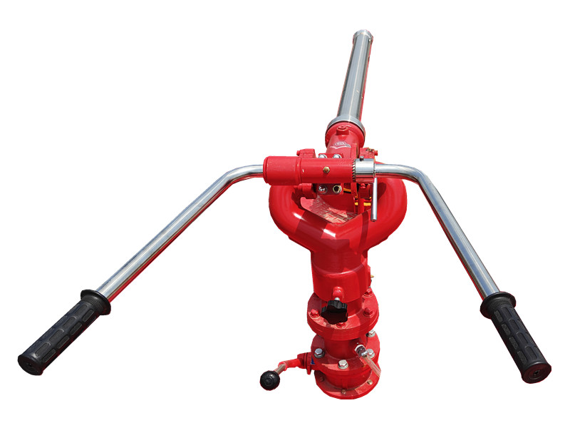
PF5-15 เครื่องตรวจสอบผงแห้งแบบคงที่ ใช้ผงแห้งเป็นตัวกลางและอาศัยฐานยึดที่มั่นคงเพื่อการฉีดพ่นที่เสถียร เหมาะสำหรับพื้นที่เคมีและคลังสินค้า และสามารถครอบคลุมพื้นผิวที่กำลังลุกไหม้ได้อย่างรวดเร็วในระยะเริ่มต้นของการเกิดเพลิงไหม้ ช่วยเพิ่มประสิทธิภาพในการดับเพลิง เดอะ เครื่องตรวจวัดผงแห้งแบบติดตั้งอยู่กับที่ PF5-15 มีโครงสร้างที่แข็งแรง ใช้งานง่าย และสามารถเชื่อมต่อกับระบบควบคุมอัตโนมัติเพื่อการเปิดใช้งานจากระยะไกลและการฉีดพ่นที่แม่นยำ - Ⅰ. เครื่องตรวจวัดผงแห้งแบบติดตั้งอยู่กับที่ PF5-15 โครงสร้าง: คุณสมบัติของเครื่องวัดปริมาณผงแห้งแบบติดตั้งอยู่กับที่ รุ่น PF5-15: ● ใช้งานได้เต็มประสิทธิภาพ; ● โครงสร้างที่เรียบง่ายและแปลกใหม่; ● ประสิทธิภาพการทำงานเสถียรและบำรุงรักษาง่าย ● แรงดันขาเข้าต่ำ; ● มาพร้อมวาล์วระบายน้ำอัตโนมัติที่มีฟังก์ชันล็อคทั้งแนวนอนและแนวตั้ง ● วัสดุ: อลูมิเนียมอัลลอยด์หล่อขึ้นรูปด้วยความแม่นยำสูง; ● หัวปืนใหญ่: ทำจากโลหะผสมอลูมิเนียม - Ⅱ. ปืนฉีดโฟม PL24 ข้อมูลจำเพาะ: แบบอย่าง ไหล - กก. /s - พิสัย - ม - แรงดันใช้งานที่กำหนด - เอ็มพีเอ - การหมุนของสนาม - ° - การหมุนในแนวนอน - ° - ล×ว×ส - มม. - น้ำหนัก - กก. - พีเอฟ5-15/40 40 ≥42 0.80 -45 ~ +70 0 ~ 360 980x340x550 28.5 - Ⅲ. การใช้งานผลิตภัณฑ์: รถดับ�
รายละเอียด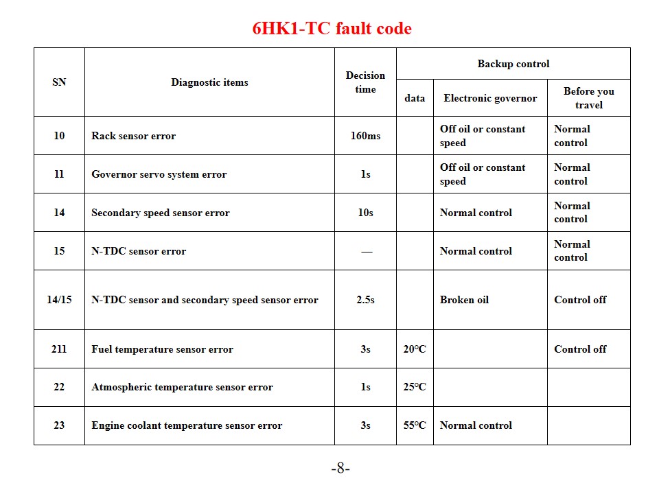
รถดับเพลิงอีซูซุ 6HK1-TC หรือเรียกอีกอย่างว่า รถดับเพลิงกู้ภัยอีซูซุ การวินิจฉัยและการแก้ไขรหัสข้อผิดพลาดของเครื่องยนต์ เครื่องยนต์ Isuzu 6HK1-TC ใช้ระบบควบคุมอิเล็กทรอนิกส์ปั๊มฉีดเชื้อเพลิง TICS ขั้นสูง และ ECU (Engine Control Unit) มีคุณสมบัติการวินิจฉัยตนเอง เมื่อระบบตรวจพบข้อผิดพลาด ไฟเตือน "CHECK ENGINE" จะสว่างขึ้นและรหัสข้อผิดพลาดที่เกี่ยวข้องจะถูกบันทึกไว้ การทำความเข้าใจการตีความและวิธีแก้ไขรหัสข้อผิดพลาดเหล่านี้จะช่วยเพิ่มประสิทธิภาพในการบำรุงรักษาเครื่องยนต์ได้อย่างมีประสิทธิผล รหัสข้อผิดพลาดทั่วไปและวิธีแก้ไข รหัสปัญหาของซีรี่ส์ P P0101 (วงจรเซ็นเซอร์วัดปริมาณอากาศไหลเข้าต่ำ) ตรวจสอบเซ็นเซอร์วัดอุณหภูมิน้ำหล่อเย็นเครื่องยนต์และสายไฟ ตรวจสอบแรงดันไฟฟ้าที่จ่ายให้กับเซ็นเซอร์และการเชื่อมต่อสายดิน เปลี่ยน ECU หรือเซ็นเซอร์หากจำเป็น P0102 (วงจรเซ็นเซอร์วัดปริมาณอากาศไหลเข้าสูง) ตรวจสอบคุณภาพน้ำมันเชื้อเพลิงและสภาพของไส้กรอง ทำความสะอาดระบบน้ำมันเชื้อเพลิง ตรวจสอบตัวควบคุมแรงดันน้ำมันเชื้อเพลิง ปั๊มน้ำมันเชื้อเพลิง และวงจรหัวฉีด P0103 (วงจรเซ็นเซอร์วัดปริมาณอากาศไหลเข้า A มีค่าสูง) ตรวจสอบวงจรสัญญาณเซ็นเซอร์ว่ามีการลัดวงจรหรือไม่ ทดสอบสถานะการทำงานของเซ็นเซอร์ เปลี่ยนเซ็นเซอร์หรือ ECU หากจำเป็น รหัสปัญหาดิจิทัล 10 (ข้อผิดพลาดเซ็นเซอร์แร็ค) ตรวจสอบเซ็นเซอร์แร็คและสายไฟ ตรวจสอบให้แน่ใจว่าการส่งสัญญาณเป็นปกติ 11 (ข้อผิดพลาดของระบบเซอร์โวควบคุมความเร็ว) ตรวจสอบสถานะการทำงานของระบบเซอร์โวควบคุมความเร็ว ทดสอบการเชื่อมต่อวงจรที่เกี่ยวข้อง 14 (ข้อผิดพลาดของเซ็นเซอร์ความเร็วเสริม) ตรวจสอบตำแหน่งการติดตั้งเซ็นเซอร์วัดความเร็วเสริม ทดสอบสัญญาณเอาต์พุตของเซ็นเซอร์ 15 (ข้อผิดพลาดเซ็นเซอร์ N-TDC) ตรวจสอบการเชื่อมต่อเซ็นเซอร์ N-TDC ตรวจสอบความถูกต้องของสัญญาณ การบำรุงรักษาระบบและมาตรการป้องกัน SN รายการวินิจฉัย ถึงเวลาตัดสินใจแล้ว การควบคุมการสำรองข้อมูล ข้อมูล ผู้ว่าการอิเล็กทรอนิกส์ ก่อนที่คุณจะเดินทาง 10 ข้อผิดพลาดของเซ็นเซอร์แร็ค 160 มิลลิวินาที ไม่ใช้น้ำมันหรือใช้ความเร็วคงที่ การควบคุมปกติ 11 ข้อผิดพลาดของระบบเซอร์โวผู้ควบคุม 1 วินาที ไม่ใช้น้ำมันหรือใช้ความเร็วคงที่ การควบคุมปกติ 14 ข้อผิดพลาดของเซ็นเซอร์ความเร็วรอง 10 วินาที การควบคุมปกติ การควบคุมปกติ 15 ข้อผิดพลาดของเซ็นเซอร์ N-TDC - การควบคุมปกติ การควบคุมปกติ 14/15 เซ็นเซอร์ N-TDC และเซ็นเซอร์ความเร็วรองเกิดข้อผิดพลาด 2.5 วินาที น้ำมันแตก ปิดระบบควบคุม 211 เซ็นเซอร์อุณหภูมิน้ำมันเชื้อเพลิงผิดพลาด 3 วินาที 20℃ ปิดระบบควบคุม 22 เซ็นเซอร์วัดอุณหภูมิบรรยากาศผิดพลาด 1 วินาที 25℃ 23 เซ็นเซอร์อุณหภูมิน้ำหล่อเย็นเครื่องยนต์ผิดพลาด 3 วินาที 55℃ การควบคุมปกติ ตัวเชื่อมต่อ หมายเลขอาคารผู้โดยสาร สัญญาณ ลวด cotor/เส้นผ่านศูนย์กลาง (ชุดสายไฟปั๊มฉีด) สว.ป. 8 เทอร์มินัล สีดำ 1 แรงดันขับแอคชูเอเตอร์ของตัวควบคุม - 1 2 ริงกิตมาเลเซีย 2 วงจรผู้ว่าการ GND-1 W/1.2 3 ตำแหน่งเป้าหมายบนชั้นวาง - 1 ยู1 2 4 แรงดันไฟฟ้าตำแหน่งแร็ค จี/1.2 5 วงจรควบคุม 5V-1 ย/1.2 6 เซ็นเซอร์สำรอง N (GND) บีอาร์/1.2 7 เซ็นเซอร์สำรอง N (SIG) 0/1.2 8 ดึงลง บี/1.2 SWP6- เทอร์มินัล สีดำ จี แรงดันขับแอคชูเอเตอร์ของตัวควบคุม - 2 อาร์/1.2 10 ตำแหน่งเป้าหมายบนชั้นวาง - 2 ล/1.2 11 วงจรควบคุม GND-2 W/1.2 12 วงจรผู้ว่าการ SIG-GND บีอาร์/1.2 13 วงจรควบคุม 5V-2 ย/1.2 SWP 3- เทอร์มินัล สีดำ 14 กลับบ้านแบบกระเผลก ว1.2 15 ซับคอยล์ (ไม่ได้ใช้งาน) BY/1.2 การ...
รายละเอียด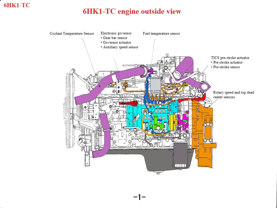
รถดับเพลิงและกู้ภัย Isuzu 6HK1 หรือเรียกอีกอย่างว่า รถดับเพลิงอีซูซุ - หากเครื่องยนต์ของรถดับเพลิงกู้ภัยอีซูซุเกิดความร้อนสูงเกินไป ควรตรวจสอบบริเวณต่อไปนี้ก่อน: 1. ระบบระบายความร้อน: ปัญหาต่างๆ เช่น พัดลมเสียหาย หม้อน้ำอุดตัน เทอร์โมสตัทเสียหาย หรือน้ำยาหล่อเย็นไม่เพียงพอ ล้วนเป็นสาเหตุที่ทำให้เครื่องยนต์ร้อนจัดได้ 2. คุณภาพและปริมาณน้ำมันเครื่อง: น้ำมันเครื่องคุณภาพต่ำหรือปริมาณน้ำมันไม่เพียงพออาจทำให้เครื่องยนต์ร้อนจัดได้เช่นกัน 3. ความเสียหายทางกลไก เช่น การระเบิดของกระบอกสูบ การแตกร้าวของปลอกกระบอกสูบ หรือรอยแตกร้าวของปลอกกระบอกสูบ ก็สามารถทำให้เกิดปรากฏการณ์นี้ได้เช่นกัน เนื่องจากเครื่องยนต์ดีเซล Isuzu 6HK1 เป็นเครื่องยนต์สำหรับงานหนัก จึงต้องปฏิบัติตามข้อกำหนดทางเทคนิคสำหรับการบำรุงรักษาอย่างเคร่งครัด โดยมีประเด็นสำคัญดังต่อไปนี้: 1. ความเข้าใจเชิงโครงสร้าง และข้อกำหนดในการถอดประกอบและประกอบ กลไกเพลาข้อเหวี่ยง-ก้านสูบ ปลอกสูบมีลักษณะการติดตั้งแบบหลวมๆ จึงต้องใช้เครื่องมือพิเศษเพื่อป้องกันไม่ให้หลุดออกมาในระหว่างการถอดประกอบ ระยะห่างมาตรฐานอยู่ที่ 0.122–0.156 มม. เส้นผ่านศูนย์กลางภายนอกของลูกสูบมีค่าความคลาดเคลื่อนที่ค่อนข้างแคบ (114.894–114.909 มม.) ในระหว่างการติดตั้ง โปรดใส่ใจกับทิศทางการเปิดของแหวนลูกสูบและการปรับ "ระยะห่างสามส่วน" (ระยะห่างด้านปลาย ระยะห่างด้านข้าง และระยะห่างด้านหลัง) ฝาครอบข้อเหวี่ยงด้านล่างเป็นโครงสร้างชิ้นเดียว และต้องยกขึ้นระหว่างการบำรุงรักษาเพื่อป้องกันการเสียรูป การปรับตั้งระบบเวลา ในระหว่างการประกอบเกียร์ ให้จัดตำแหน่งเครื่องหมายบนเฟืองข้อเหวี่ยงและเฟืองตัวกลางให้ตรงกัน เครื่องหมาย B บนเพลาลูกเบี้ยวต้องอยู่เสมอกับพื้นผิวของฝาสูบ เครื่องยนต์ควรอยู่ที่จุดศูนย์ตายบนของการอัดในกระบอกสูบแรก เมื่อติดตั้งปั๊มฉีดเชื้อเพลิง ให้จัดตำแหน่งตัวชี้จังหวะให้ตรงกับจุด S บนขั้วต่อ และจัดตำแหน่งเครื่องหมายปรับจังหวะการฉีดให้ตรงกับตัวชี้บนตัวปั๊ม - มอเตอร์ DC แบบเชิงเส้นจะดันขดลวดขึ้นและลงตามสัญญาณเอาต์พุตจากชุดควบคุม - ก้านเชื่อมต่อที่ติดตั้งอยู่บนชุดคอยล์จะส่งการเคลื่อนที่ขึ้นลงของคอยล์ไปยังบล็อกเชื่อมต่อ ซึ่งบล็อกเชื่อมต่อจะติดตั้งอยู่ที่ปลายของแร็ค ภายใต้แรงดันของบล็อกเชื่อมต่อ แร็คจะเคลื่อนที่ไปทางซ้ายและขวาเพื่อเปลี่ยนปริมาณการฉีดเชื้อเพลิง เมื่อชุดคอยล์เคลื่อนที่ขึ้น ก้านเชื่อมต่อจะดันแร็คเพื่อเพิ่มทิศทางการไหลของน้ำมัน ในทางกลับกัน เมื่อชุดคอยล์เคลื่อนที่ลง แร็คจะเคลื่อนที่ไปในทิศทางลดการไหลของน้ำมัน และหน้าที่ของก้านเชื่อมต่อคือการแปลงการเคลื่อนที่ในแนวดิ่งเป็นการเคลื่อนที่ในแนวดิ่งของแร็ค - บล็อกทองแดงถูกติดตั้งไว้ที่ส่วนบนของบล็อกเชื่อมต่อเพื่อทำหน้าที่เป็นเซ็นเซอร์ตรวจจับการเคลื่อนที่ของแร็ค เซ็นเซอร์นี้จะตรวจจับการเคลื่อนที่ของแร็คและส่งค่านี้กลับไปยังหน่วยควบคุม เพื่อให้สามารถเปรียบเทียบการเคลื่อนที่ของแร็คจริงและการเคลื่อนที่ของแร็คเป้าหมายได้อย่างต่อเนื่องจนกว่าความแตกต่างระหว่างทั้งสองจะเข้าใกล้ศูนย์ กระบวนการนี้มีความสำคัญมากต่อการควบคุมความแม่นยำและการตอบสนอง 2. จุดสำคัญในการบำรุงรักษาระบบ ระบบหล่อลื่นและระบายความร้อน ระยะเวลาเปลี่ยนถ่ายน้ำมันเครื่อง: น้ำมันเบนซิน: ทุก 5,000 กิโลเมตร หรือ 6 เดือน; น้ำมันสังเคราะห์: 8,000–10,000 กิโลเมตร ช่องรับน้ำหล่อเย็นมีลักษณะเป็นขั้นบันได และต้องถอดชิ้นส่วนตามลำดับเพื่อการบำรุงรักษา ควรเปลี่ยนน้ำยาหล่อเย็นทุกสองปีหรือ 40,000 กิโลเมตร ระบบจ่ายเชื้อเพลิงและอากาศ เปลี่ยนไส้กร...
รายละเอียด
โปรดอ่านต่อ ติดตามข่าวสาร สมัครรับข้อมูล และเรายินดีรับฟังความคิดเห็นของคุณ

 รองรับเครือข่าย IPv6

 ไทย
ไทย English
 français
 Deutsch
 русский
 italiano
 español
 português
 Nederlands
 العربية
 日本語
日本語 한국의
한국의 Türkçe
 Melayu
 Tiếng Việt
 Indonesia
  中文
中文 қазақ
қазақ Filipino
 မြန်မာ
 српски