ฝากข้อความ
หากคุณสนใจในผลิตภัณฑ์ของเราและต้องการทราบรายละเอียดเพิ่มเติม โปรดฝากข้อความไว้ที่นี่ เราจะตอบกลับคุณโดยเร็วที่สุด

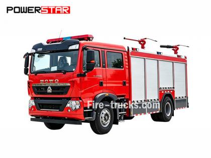
คู่มือการบำรุงรักษาเครื่องยนต์สำหรับรถดับเพลิงอีซูซุ รุ่น 4HK1-TC หรือเรียกอีกอย่างว่า คู่มือซ่อมเครื่องยนต์ รถดับเพลิงอีซูซุ หรือหนังสือวิศวกรของ รถดับเพลิงอีซูซุ -
เครื่องยนต์ Isuzu Fire Truck 4HK1-TC เป็นเครื่องยนต์ดีเซลสมรรถสูงที่ใช้กันอย่างแพร่หลายในรถดับเพลิง มีชื่อเสียงในด้านความน่าเชื่อถือ ความทนทาน และประสิทธิภาพสูง เพื่อให้มั่นใจถึงการทำงานที่เสถียรในระยะยาวของเครื่องยนต์ การบำรุงรักษาและการซ่อมแซมอย่างสม่ำเสมอจึงเป็นสิ่งสำคัญ บทความนี้จะแนะนำเนื้อหาหลักของคู่มือการบำรุงรักษาเครื่องยนต์ Isuzu Fire Truck 4HK1-TC โดยสังเขป เพื่อช่วยให้บุคลากรด้านการบำรุงรักษาเข้าใจและใช้งานได้ดียิ่งขึ้น
1. ภาพรวมเครื่องยนต์
เครื่องยนต์ 4HK1-TC เป็นเครื่องยนต์ดีเซลเทอร์โบชาร์จ 4 สูบเรียง ขนาด 5.2 ลิตร กำลังสูงสุด 190 แรงม้า เครื่องยนต์ใช้ระบบฉีดเชื้อเพลิงแบบคอมมอนเรลขั้นสูงและหน่วยควบคุมอิเล็กทรอนิกส์ (ECU) เพื่อให้ประหยัดเชื้อเพลิงและลดการปล่อยมลพิษ
2. การบำรุงรักษาประจำวัน
การบำรุงรักษาประจำวันเป็นพื้นฐานสำคัญในการรับประกันการทำงานปกติของเครื่องยนต์ คู่มือการบำรุงรักษาได้ระบุรายละเอียดรายการตรวจสอบประจำวันไว้อย่างครบถ้วน รวมถึงการตรวจสอบระดับน้ำมันเครื่องและน้ำหล่อเย็น การทำความสะอาดหรือเปลี่ยนไส้กรองอากาศ การเปลี่ยนไส้กรองน้ำมันเชื้อเพลิง เป็นต้น นอกจากนี้ คู่มือยังให้คำแนะนำเกี่ยวกับการเปลี่ยนถ่ายน้ำมันเครื่องและไส้กรองน้ำมันเครื่องเป็นประจำ ซึ่งโดยทั่วไปควรเปลี่ยนทุกๆ 5,000 กิโลเมตร หรือทุกๆ 6 เดือน
3. การวินิจฉัยปัญหา
คู่มือการบำรุงรักษาประกอบด้วยกระบวนการวินิจฉัยข้อผิดพลาดโดยละเอียด เพื่อช่วยให้เจ้าหน้าที่ฝ่ายบำรุงรักษาสามารถค้นหาและแก้ไขปัญหาได้อย่างรวดเร็ว คู่มือนี้แสดงรายการรหัสข้อผิดพลาดทั่วไปและความหมาย พร้อมทั้งเสนอวิธีแก้ไขที่เกี่ยวข้อง ตัวอย่างเช่น หากเครื่องยนต์มีกำลังไม่เพียงพอ คู่มือจะแนะนำให้เจ้าหน้าที่ฝ่ายบำรุงรักษาตรวจสอบระบบเชื้อเพลิง เทอร์โบชาร์จเจอร์ และระบบไอเสีย เป็นต้น
4. การยกเครื่องและเปลี่ยนชิ้นส่วน
สำหรับเครื่องยนต์ที่ต้องการการซ่อมแซมหรือเปลี่ยนชิ้นส่วน คู่มือการบำรุงรักษาจะให้ขั้นตอนและข้อควรระวังโดยละเอียด ตัวอย่างเช่น เมื่อเปลี่ยนชิ้นส่วนสำคัญ เช่น แหวนลูกสูบ ตัวนำวาล์ว และแบริ่ง คู่มือจะระบุขั้นตอนการถอดและติดตั้งโดยละเอียด รวมถึงเครื่องมือที่จำเป็นและข้อกำหนดแรงบิด
5. ข้อควรระวังด้านความปลอดภัย
คู่มือการบำรุงรักษาเน้นย้ำเป็นพิเศษถึงความสำคัญของการใช้งานอย่างปลอดภัย ก่อนดำเนินการบำรุงรักษาใดๆ คุณต้องตรวจสอบให้แน่ใจว่าเครื่องยนต์เย็นสนิทแล้วและได้ตัดการจ่ายไฟแล้ว นอกจากนี้ คู่มือยังให้คำแนะนำเกี่ยวกับการใช้อุปกรณ์ป้องกันส่วนบุคคล เช่น ถุงมือ แว่นตา และชุดป้องกันอีกด้วย
มาตรา 1A
ระบบควบคุมเครื่องยนต์
สารบัญ
หน้าหนังสือ
[if supportFields]>สารบัญ \h \z \t "1A,1,1A-,2"
ระบบควบคุมเครื่องยนต์
[if supportFields]>
4
[if gte mso 9]>
ข้อควรระวัง
[if supportFields]>
4
[if gte mso 9]>
หน้าที่และหลักการทำงาน
[if supportFields]>
5
[if gte mso 9]>
แผนภาพการจัดเรียงชิ้นส่วน
[if supportFields]>
21
[if gte mso 9]>
แผนผังวงจร
[if supportFields]>
25
[if gte mso 9]>
วิธีการวินิจฉัยปัญหา
[if supportFields]>
42
[if gte mso 9]>
ขั้นตอนการวินิจฉัยความผิดพลาดโดยใช้เครื่องมือวินิจฉัยความผิดพลาด
[if supportFields]>
48
[if gte mso 9]>
ภาพรวมการตรวจสอบการทำงาน
[if supportFields]>
50
[if gte mso 9]>
การสอบถาม
[if supportFields]>
51
[if gte mso 9]>
การตรวจสอบระบบควบคุมเครื่องยนต์
[if supportFields]>
53
[if gte mso 9]>
รายการข้อมูลมิเตอร์วินิจฉัยข้อผิดพลาด
[if supportFields]>
55
[if gte mso 9]>
เนื้อหารายการข้อมูลของมิเตอร์วินิจฉัยข้อผิดพลาด
[if supportFields]>
58
[if gte mso 9]>
เอาต์พุตของมิเตอร์วินิจฉัยข้อผิดพลาด
[if supportFields]>
64
[if gte mso 9]>
มิเตอร์วินิจฉัยข้อผิดพลาดเริ่มทำงานล้มเหลว
[if supportFields]>
65
[if gte mso 9]>
การวินิจฉัยข้อผิดพลาด การสื่อสารของมิเตอร์ (อ้างอิง)
[if supportFields]>
67
[if gte mso 9]>
การสื่อสารล้มเหลวกับ ECM (อ้างอิง)
[if supportFields]>
71
[if gte mso 9]>
การยืนยันการเริ่มต้นระบบ
[if supportFields]>
74
[if gte mso 9]>
ไฟเตือนเครื่องยนต์ MIL สว่างขึ้นเพื่อยืนยันระบบวงจรไฟฟ้า
[if supportFields]>
77
[if gte mso 9]>
ไฟเตือนเครื่องยนต์ (MIL) กระพริบเพื่อยืนยันระบบวงจรไฟฟ้า
[if supportFields]>
78
[if gte mso 9]>
การตรวจสอบระบบควบคุมการหมุนเวียนก๊าซไอเสีย (EGR)
[if supportFields]>
80
[if gte mso 9]>
การตรวจสอบระบบควบคุมการอุ่นเครื่อง
[if supportFields]>
84
[if gte mso 9]>
การตรวจสอบระบบเบรกไอเสีย/ระบบควบคุมการจำกัดการไหลของอากาศเข้า
[if supportFields]>
87
[if gte mso 9]>
ภาพรวมรหัสข้อผิดพลาดในการวินิจฉัย (DTC)
[if supportFields]>
92
[if gte mso 9]>
รหัสข้อผิดพลาด DTC P0016 (รหัสแฟลช 16)
[if supportFields]>
95
[if gte mso 9]>
รหัสข้อผิดพลาด DTC P0087 (รหัสแฟลช 225)
[if supportFields]>
97
[if gte mso 9]>
รหัสข้อผิดพลาด DTC P0088 (รหัสแฟลช 118)
[if supportFields]>
103
[if gte mso 9]>
รหัสข้อผิดพลาด DTC P0089 (รหัสแฟลช 151)
[if supportFields]>
109
[if gte mso 9]>
รหัสข้อผิดพลาด DTC P0091, P0092 (รหัสแฟลช 247)
[if supportFields]>
112
[if gte mso 9]>
รหัสข้อผิดพลาด DTC P0093 (รหัสแฟลช 227)
[if supportFields]>
116
[if gte mso 9]>
รหัสข้อผิดพลาด DTC P0107, P0108 (รหัสแฟลช 32)
[if supportFields]>
122
[if gte mso 9]>
รหัสข้อผิดพลาด DTC P0112, P0113 (รหัสแฟลช 22)
[if supportFields]>
127
[if gte mso 9]>
รหัสข้อผิดพลาด DTC P0117, P0118 (รหัสแฟลช 23)
[if supportFields]>
132
[if gte mso 9]>
รหัสข้อผิดพลาด DTC P0122, P0123 (รหัสแฟลช 43)
[if supportFields]>
137
[if gte mso 9]>
รหัสข้อผิดพลาด DTC P0182, P0183 (รหัสแฟลช 211)
[if supportFields]>
142
[if gte mso 9]>
รหัสข้อผิดพลาด DTC P0192, P0193 (รหัสแฟลช 245)
[if supportFields]>
147
[if gte mso 9]>
[if supportFields]> DTC P0201, P0202, P0203, P0204 (รหัสแฟลช 271, 272, 273, 274)................................................... 1A-157
รหัสข้อผิดพลาด DTC P0217 (รหัสแฟลช 542)...................................................................................................... 1A-170
รหัสข้อผิดพลาด DTC P0219 (รหัสแฟลช 543)...................................................................................................... 1A-172
รหัสข้อผิดพลาด DTC P0234 (รหัสแฟลช 42)........................................................................................................ 1A-175
รหัสข้อผิดพลาด DTC P0299 (รหัสแฟลช 65)........................................................................................................ 1A-178
รหัสข้อผิดพลาด DTC P0335 (รหัสแฟลช 15)........................................................................................................ 1A-182
รหัสข้อผิดพลาด DTC P0336 (รหัสแฟลช 15)........................................................................................................ 1A-187
รหัสข้อผิดพลาด DTC P0340 (รหัสแฟลช 14)........................................................................................................ 1A-190
รหัสข้อผิดพลาด DTC P0341 (รหัสแฟลช 14)........................................................................................................ 1A-195
รหัสข้อผิดพลาด DTC P0380 (รหัสแฟลช 66)........................................................................................................ 1A-198
รหัสข้อผิดพลาด DTC P0381 (รหัสแฟลช 67)........................................................................................................ 1A-201
รหัสข้อผิดพลาด DTC P0404 (รหัสแฟลช 45)........................................................................................................ 1A-205
รหัสข้อผิดพลาด DTC P0409 (รหัสแฟลช 44)........................................................................................................ 1A-208
DTC P0477, P0478 (รหัสแฟลช 46)............................................................................................. 1A-212
รหัสข้อผิดพลาด DTC P0500 (รหัสแฟลช 25)........................................................................................................ 1A-216
DTC P0502, P0503 (รหัสแฟลช 25)............................................................................................. 1A-218
รหัสข้อผิดพลาด DTC P0563 (รหัสแฟลช 35)........................................................................................................ 1A-223
รหัสข้อผิดพลาด DTC P0601 (รหัสแฟลช 53)........................................................................................................ 1A-225
รหัสข้อผิดพลาด DTC P0602 (รหัสแฟลช 154)...................................................................................................... 1A-226
DTC P0604, P0606, P060B (รหัสแฟลช 153, 51, 36).................................................................... 1A-228
รหัสข้อผิดพลาด DTC P0641 (รหัสแฟลช 55)........................................................................................................ 1A-230
รหัสข้อผิดพลาด DTC P0650 (รหัสแฟลช 77)........................................................................................................ 1A-233
รหัสข้อผิดพลาด DTC P0651 (รหัสแฟลช 56)........................................................................................................ 1A-237
DTC P0685, P0687 (รหัสแฟลช 416)........................................................................................... 1A-241
รหัสข้อผิดพลาด DTC P0697 (รหัสแฟลช 57)........................................................................................................ 1A-245
รหัสข้อผิดพลาด DTC P1093 (รหัสแฟลช 227)...................................................................................................... 1A-248
DTC P1261, P1262 (รหัสแฟลช 34)............................................................................................. 1A-253
รหัสข้อผิดพลาด DTC P1404 (รหัสแฟลช 45)........................................................................................................ 1A-255
รหัสข้อผิดพลาด DTC P1621 (รหัสแฟลช 54)........................................................................................................ 1A-257
รหัส DTC P2122, P2123 (รหัสแฟลช 121)........................................................................................... 1A-258
รหัส DTC P2127, P2128 (รหัสแฟลช 122)........................................................................................... 1A-264
รหัสข้อผิดพลาด DTC P2138 (รหัสแฟลช 124)...................................................................................................... 1A-270
DTC P2146, P2149 (รหัสแฟลช 158)........................................................................................... 1A-273
DTC P2228, P2229 (รหัสแฟลช 71)............................................................................................. 1A-279
รหัสข้อผิดพลาด DTC P253A (รหัสแฟลช 28)....................................................................................................... 1A-284
รหัสข้อผิดพลาด DTC P256A (รหัสแฟลช 31)....................................................................................................... 1A-287
DTC U0073 (รหัสแฟลช 84)....................................................................................................... 1A-291
การวินิจฉัยอาการ................................................................................................................... 1A-296
ปรากฏการณ์: ความไม่ต่อเนื่อง............................................................................................................ 1A-297
อาการ: สตาร์ทติดยาก........................................................................................................ 1A-300
ปรากฏการณ์: รอบเครื่องยนต์กระชาก, รอบเดินเบาไม่คงที่ หรือเครื่องยนต์ดับ.................................................................... 1A-303
ปรากฏการณ์: รอบเดินเบาสูง.................................................................................................... 1A-306
อาการ: การหยุดฉุกเฉิน......................................................................................................... 1A-307
อาการ: การเปลี่ยนฉุกเฉิน..................................................................................................... 1A-309
อาการ: กำลังเครื่องยนต์ต่ำ, อัตราเร่งไม่ขึ้น หรือการตอบสนองช้า........................................................... 1A-311
ปรากฏการณ์: การทำงานไม่ต่อเนื่อง, ความล้มเหลวในการเร่งความเร็ว................................................................... 1A-314
อาการ: เสียงการเผาไหม้...................................................................................................... 1A-316
อาการ: อัตราการประหยัดน้ำมันเชื้อเพลิงต่ำ.................................................................................... 1A-317
ปรากฏการณ์: ควันดำจากท่อไอเสีย................................................................................... 1A-319
อาการ: ควันขาวออกจากท่อไอเสีย.................................................................................. 1A-321
พารามิเตอร์เซ็นเซอร์หลัก.............................................................................................................. 1A-323
เครื่องมือพิเศษ............................................................................................................................. 1A-325
โปรแกรม............................................................................................................................ 1A-326
กฎการเขียนโปรแกรม...................................................................................................................... 1A-326
โปรแกรม............................................................................................................................ 1A-326
การเรียนรู้ปั๊มฉีด.............................................................................................................. 1A-328
การปรับแต่ง............................................................................................................................... 1A-328
การใช้เครื่องมือทดสอบวงจร
ในกรณีที่ทำการวินิจฉัยตามโปรแกรมวินิจฉัย ห้ามใช้หลอดไฟทดสอบสำหรับการวินิจฉัยระบบไฟฟ้าของระบบส่งกำลัง เว้นแต่จะระบุไว้เป็นอย่างอื่น ในกรณีที่จะใช้ขั้วต่อโพรบสำหรับโปรแกรมวินิจฉัย โปรดใช้ชุดอะแดปเตอร์ทดสอบขั้วต่อ 5-8840-2835-0
ชิ้นส่วนไฟฟ้าที่มีจำหน่ายในตลาด
ชิ้นส่วนไฟฟ้าที่หาซื้อได้ทั่วไป หมายถึง ชิ้นส่วนไฟฟ้าที่ซื้อจากตลาดเพื่อนำมาติดตั้งในรถยนต์ เนื่องจากชิ้นส่วนเหล่านี้ไม่ได้ถูกนำมาพิจารณาในขั้นตอนการออกแบบยานยนต์ จึงควรให้ความสำคัญกับชิ้นส่วนเหล่านี้เมื่อใช้งาน
คำเตือน:
ส่วนประกอบไฟฟ้าที่หาซื้อได้ทั่วไปในท้องตลาดจะต้องต่อสายไฟและสายดินเข้ากับวงจรโดยไม่เกี่ยวข้องกับวงจรระบบควบคุมไฟฟ้า
แม้ว่าชิ้นส่วนไฟฟ้าที่หาซื้อได้ทั่วไปในท้องตลาดจะสามารถนำมาใช้ได้ แต่ในบางกรณีอาจทำให้ระบบควบคุมไฟฟ้าทำงานผิดปกติได้ ซึ่งรวมถึงอุปกรณ์ที่ไม่เชื่อมต่อกับระบบไฟฟ้า เช่น โทรศัพท์มือถือ วิทยุ ดังนั้น ในการวินิจฉัยระบบขับเคลื่อน ให้ตรวจสอบก่อนว่ามีการติดตั้งชิ้นส่วนไฟฟ้าที่หาซื้อได้ทั่วไปดังกล่าวหรือไม่ หากมี ให้ถอดออกจากรถ หากปัญหายังคงอยู่หลังจากถอดชิ้นส่วนแล้ว ให้ทำตามขั้นตอนการวินิจฉัยทั่วไปต่อไป
ความเสียหายเนื่องจากไฟฟ้าสถิต
เนื่องจากชิ้นส่วนอิเล็กทรอนิกส์ในระบบควบคุมไฟฟ้าสามารถทำงานได้ภายใต้แรงดันไฟฟ้าต่ำมาก จึงทำให้ชิ้นส่วนเหล่านี้เสียหายได้ง่ายจากไฟฟ้าสถิต (ESD) ชิ้นส่วนอิเล็กทรอนิกส์บางชิ้นจะเสียหายจากไฟฟ้าสถิตที่แรงดันต่ำกว่า 100 โวลต์ ซึ่งมนุษย์ไม่สามารถรับรู้ได้ ไฟฟ้าสถิตที่มนุษย์สามารถรับรู้ได้นั้นต้องใช้แรงดันไฟฟ้า 4000 โวลต์ ในหลายกรณี มนุษย์จะพกพาไฟฟ้าสถิตติดตัวไปด้วย ซึ่งการเกิดไฟฟ้าสถิตจากการเสียดสีและการเหนี่ยวนำเป็นสาเหตุที่พบได้บ่อยที่สุด
● เมื่อคนขยับตัวไปมาบนที่นั่ง จะเกิดการเสียดสีจนเกิดไฟฟ้าสถิตขึ้น
● เมื่อบุคคลที่สวมรองเท้าหุ้มฉนวนอยู่ใกล้กับวัตถุที่มีประจุไฟฟ้าสูง การเหนี่ยวนำไฟฟ้าสถิตจะเกิดขึ้นในขณะที่บุคคลนั้นสัมผัสพื้น บุคคลนั้นจะถูกไฟฟ้าสถิตดูดเมื่อประจุที่มีขั้วเดียวกันมาพบกับประจุที่มีขั้วตรงข้าม เนื่องจากไฟฟ้าสถิตจะก่อให้เกิดความเสียหาย จึงควรระมัดระวังในการใช้งานชิ้นส่วนอิเล็กทรอนิกส์และทดสอบก่อนใช้งาน
คำเตือน:
โปรดปฏิบัติตามกฎต่อไปนี้เพื่อป้องกันความเสียหายจากไฟฟ้าสถิต:
● ห้ามสัมผัสขั้วต่อของ ECM และชิ้นส่วนอิเล็กทรอนิกส์ที่บัดกรีติดอยู่กับแผ่นหลังวงจร ECM
● ห้ามแกะกล่องอุปกรณ์จัดสวนจนกว่าการเตรียมการติดตั้งบางส่วนจะเสร็จสมบูรณ์
● ต่อสายดินของกล่องบรรจุภัณฑ์และตัวรถให้เรียบร้อยก่อนนำชิ้นส่วนออกจากกล่องบรรจุภัณฑ์
● หากมีการขยับตัวไปมาบนที่นั่ง หรือลุกขึ้นจากท่ายืน หรือใช้งานชิ้นส่วนขณะเคลื่อนที่ในระยะหนึ่ง โปรดตรวจสอบให้แน่ใจว่าได้วางชิ้นส่วนลงบนพื้นปกติก่อนติดตั้ง
ระบบควบคุมเครื่องยนต์ (คอมมอนเรล)
ภาพรวมและรายละเอียดของระบบ
ระบบควบคุมเครื่องยนต์ หมายถึง ระบบควบคุมทางไฟฟ้าที่ใช้ควบคุมเครื่องยนต์ให้ทำงานในโหมดการเผาไหม้ที่เหมาะสมที่สุดตามสภาพการขับขี่ ประกอบด้วยส่วนต่างๆ ดังต่อไปนี้:
● ระบบฉีดเชื้อเพลิงควบคุมด้วยระบบอิเล็กทรอนิกส์ (แบบรางร่วม)
● EGR
นอกจากนี้ ระบบควบคุมเครื่องยนต์ยังประกอบด้วยฟังก์ชันควบคุมระบบดังต่อไปนี้
● ระบบควบคุมการอุ่นเครื่อง
● กำลังส่งออกของเครื่องยนต์แบบหมุน
● ฟังก์ชันการสื่อสารและการวินิจฉัยตนเอง
[endif]
[if gte vml 1]>
ระบบฉีดเชื้อเพลิงควบคุมด้วยอิเล็กทรอนิกส์ (แบบรางร่วม)
ระบบคอมมอนเรลประกอบด้วยห้องแรงดันและหัวฉีด ห้องแรงดันถูกออกแบบมาเพื่อเก็บเชื้อเพลิงที่มีแรงดันสูงและเรียกว่าคอมมอนเรล ส่วนหัวฉีดมีวาล์วโซลินอยด์ควบคุมด้วยระบบอิเล็กทรอนิกส์เพื่อฉีดเชื้อเพลิงที่มีแรงดันสูงเข้าไปในห้องเผาไหม้ เนื่องจากระบบควบคุมการฉีด (แรงดันการฉีด อัตราการฉีด และเวลาการฉีด) ถูกควบคุมโดย ECM ระบบคอมมอนเรลจึงช่วยให้สามารถควบคุมความเร็วและภาระของเครื่องยนต์ได้อย่างอิสระ แม้ว่าความเร็วของเครื่องยนต์จะต่ำ แรงดันการฉีดก็ยังคงคงที่ ซึ่งจะช่วยลดควันดำที่เกิดขึ้นขณะสตาร์ทและเร่งความเร็วของเครื่องยนต์ดีเซลได้อย่างมาก ด้วยการควบคุมนี้ ก๊าซไอเสียจะสะอาดขึ้น ปริมาณไอเสียจะน้อยลง และกำลังขับจะสูงขึ้น
การควบคุมปริมาณการฉีด
ระบบนี้ควบคุมขดลวดหัวฉีดตามสัญญาณที่ได้รับจากความเร็วรอบเครื่องยนต์และการเหยียบคันเร่ง และควบคุมปริมาณการฉีดเชื้อเพลิงเพื่อให้ได้ปริมาณที่เหมาะสมที่สุด
การควบคุมแรงดันการฉีด
เพื่อให้สามารถฉีดเชื้อเพลิงด้วยแรงดันสูงได้แม้ความเร็วรอบเครื่องยนต์ต่ำ จำเป็นต้องควบคุมแรงดันเชื้อเพลิงภายในรางร่วม (common rail) คำนวณแรงดันที่เหมาะสมในรางร่วมตามความเร็วรอบเครื่องยนต์และปริมาณการฉีดเชื้อเพลิง ปล่อยเชื้อเพลิงในปริมาณที่เหมาะสมผ่านปั๊มฉีดควบคุม และส่งเชื้อเพลิงไปยังรางร่วมภายใต้แรงดัน
การควบคุมเวลาการฉีด
มันทำหน้าที่แทนฟังก์ชันการตั้งเวลา โดยจะคำนวณเวลาการฉีดเชื้อเพลิงที่เหมาะสมตามความเร็วรอบเครื่องยนต์และปริมาณการฉีด แล้วจึงควบคุมหัวฉีด
การควบคุมอัตราการฉีด
เพื่อเพิ่มประสิทธิภาพการเผาไหม้ในกระบอกสูบ ให้ฉีดเชื้อเพลิงเล็กน้อยก่อนการจุดระเบิด (pre-injection) หลังจากจุดระเบิดแล้ว ให้ทำการฉีดเชื้อเพลิงครั้งที่สอง (main injection) ควบคุมเวลาและปริมาณการฉีดผ่านหัวฉีด (คอยล์หัวฉีด)
 [endif]
ระบบเชื้อเพลิง
ระบบคอมมอนเรลประกอบด้วยระบบแรงดันเชื้อเพลิง 2 ระบบ
● ท่อทางเข้าแรงดันต่ำ: ระหว่างถังเชื้อเพลิงและปั๊มฉีดเชื้อเพลิง
● ท่อแรงดันสูง: เชื่อมระหว่างปั๊มฉีดและหัวฉีด
น้ำมันเชื้อเพลิงถูกดูดจากถังน้ำมันเข้าสู่ปั๊มฉีด และถูกเพิ่มแรงดันในปั๊มเพื่อส่งไปยังรางจ่ายน้ำมันเชื้อเพลิง ณ จุดนี้ สัญญาณจาก ECM จะควบคุมวาล์วควบคุมการดูด (ตัวควบคุมแรงดันรางร่วม) เพื่อควบคุมปริมาณเชื้อเพลิงที่จ่ายไปยังรางร่วม
แผนภาพระบบเชื้อเพลิง
[if gte vml 1]>
|
สำคัญ 1. คอมมอนเรล 2. วาล์วจำกัดแรงดัน 3. ท่อส่งกลับของหัวฉีด 4. หัวฉีด 5. ท่อส่งน้ำมันเชื้อเพลิงกลับ 6. ท่อส่งเชื้อเพลิง |
7. ถังน้ำมันเชื้อเพลิง 8. วาล์วระบายอากาศ 9. ปั๊มสตาร์ท 10. ตัวกรองน้ำมันเชื้อเพลิง (พร้อมตัวแยกน้ำมันและน้ำ) 11. วาล์วส่งกลับ 12. ปั๊มฉีดเชื้อเพลิง |
อีจีอาร์ (การหมุนเวียนก๊าซไอเสีย)
ระบบ EGR จะนำก๊าซไอเสียส่วนหนึ่งกลับเข้าสู่ท่อร่วมไอดี ส่งผลให้ลดการปล่อยก๊าซไนโตรเจนออกไซด์ (NOx) ระบบ EGR ช่วยให้การขับขี่ราบรื่นและลดการปล่อยก๊าซไอเสียได้ กระแสไฟฟ้าควบคุมจาก EGR จะควบคุมวาล์วโซลินอยด์ให้ทำงานและควบคุมการยกตัวของวาล์ว EGR นอกจากนี้ ระบบยังตรวจจับการยกตัวของวาล์วที่แท้จริงด้วยเซ็นเซอร์ตำแหน่ง EGR เพื่อให้สามารถควบคุม EGR ได้อย่างละเอียด
ระบบ EGR จะเริ่มทำงานเมื่อความเร็วรอบเครื่องยนต์ อุณหภูมิน้ำหล่อเย็นเครื่องยนต์ อุณหภูมิไอดี และความดันบรรยากาศเป็นไปตามเงื่อนไข จากนั้นระบบจะคำนวณการเปิดวาล์วตามความเร็วรอบเครื่องยนต์และปริมาณการฉีดเชื้อเพลิงเป้าหมาย โดยอิงจากค่าการเปิดวาล์วที่คำนวณได้ ระบบจะกำหนดภาระการขับเคลื่อนของโซลินอยด์วาล์วแล้วจึงขับเคลื่อนวาล์ว ในระหว่างการทำงานของ EGR ลิ้นปีกผีเสื้อไอดีจะปิดลงเพื่อให้ความดันภายในท่อไอดีถึงค่าเป้าหมาย
[if gte vml 1]>
[endif]
[ถ้า !mso]
|
[endif]
[ถ้า !mso]
|
[endif]
[ถ้า !mso]
|
[endif]
[ถ้า !mso]
|
|
สำคัญ 1. อีซีเอ็ม 2. เซ็นเซอร์ตำแหน่ง EGR 3. วาล์ว EGR 4. ตัวระบายความร้อน EGR |
5. วาล์วปีกผีเสื้อไอดี
|
การควบคุมการวอร์มร่างกาย
ระบบควบคุมการอุ่นเครื่อง
ระบบควบคุมการอุ่นเครื่องได้รับการออกแบบมาเพื่อช่วยให้สตาร์ทเครื่องยนต์ได้ง่ายขึ้นในอุณหภูมิต่ำ และลดควันขาวและเสียงดัง เมื่อสวิตช์สตาร์ททำงาน ECM จะตรวจจับอุณหภูมิของน้ำหล่อเย็นเครื่องยนต์ตามสัญญาณจากเซ็นเซอร์อุณหภูมิของน้ำหล่อเย็นเครื่องยนต์ (ECT) เพื่อปรับเวลาการอุ่นเครื่องและสร้างสภาวะการสตาร์ทที่เหมาะสมสำหรับเครื่องยนต์ นอกจากนี้ ความร้อนที่เหลือจากการอุ่นเครื่องยังช่วยรักษาเสถียรภาพการเดินเบา ECM จะกำหนดเวลาการอุ่นเครื่องตามอุณหภูมิของน้ำหล่อเย็นเครื่องยนต์เพื่อสั่งการให้รีเลย์อุ่นเครื่องและไฟแสดงสถานะทำงาน
[endif]
[if gte vml 1]>
ภาพรวมของการควบคุมเบรกไอเสีย
ท่อไอเสียของระบบเบรกไอเสียมีวาล์วอยู่ภายใน การปิดวาล์วจะเพิ่มแรงต้านการเคลื่อนที่ของไอเสียและเพิ่มประสิทธิภาพการเบรกของเครื่องยนต์ วาล์วเบรกไอเสียทำงานตามแรงดันสุญญากาศ แรงดันสุญญากาศของเบรกไอเสียถูกควบคุมโดยการเปิดและปิดของวาล์วโซลินอยด์ ECM จะเปิดใช้งานวาล์วโซลินอยด์หากความเร็วรอบเครื่องยนต์สูงกว่า 575 รอบต่อนาทีและตรงตามเงื่อนไขการทำงานของเบรกไอเสียทั้งหมด
สภาวะการทำงานของเบรกไอเสีย
● สวิตช์เบรกไอเสียเปิดอยู่
● คันเร่งไม่ได้ถูกเหยียบ
● ไม่สามารถตรวจจับความผิดปกติของเซ็นเซอร์ตำแหน่งแป้นเหยียบเร่ง (APP), วงจรเบรกไอเสียผิดปกติ, สวิตช์คลัตช์ผิดปกติ, สวิตช์เซ็นเซอร์ APP ผิดปกติ, สวิตช์ A/D ผิดปกติ เป็นต้น
● เหยียบแป้นคลัตช์ไม่ลง
● แรงดันไฟฟ้าของระบบสูงกว่า 24V
● ความเร็วของยานพาหนะเกินช่วงที่กำหนด
อีซีเอ็ม
ภาพรวมของ ECM
[if gte vml 1]>
ECM ตรวจสอบข้อมูลจากเซ็นเซอร์ทุกตัวตลอดเวลาเพื่อควบคุมระบบส่งกำลัง ECM ทำหน้าที่วินิจฉัยระบบเพื่อตรวจจับปัญหาการทำงานของระบบ แจ้งเตือนผู้ขับขี่ผ่านไฟเตือนเครื่องยนต์ (MIL) และบันทึกรหัสข้อผิดพลาด (DTC) ในเวลาเดียวกัน รหัสข้อผิดพลาด (DTC) จะระบุจุดที่มีปัญหาเพื่อช่วยช่างซ่อมบำรุง
ฟังก์ชัน ECM
ECM ส่งออกแรงดันไฟฟ้า 5V เพื่อจ่ายไฟให้กับเซ็นเซอร์และสวิตช์ต่างๆ อย่างไรก็ตาม เนื่องจากพลังงานถูกจ่ายผ่านความต้านทานของ ECM หลอดไฟทดสอบที่เชื่อมต่อกับวงจรจะไม่ติดแม้ว่าความต้านทานจะสูงมากก็ตาม ในบางกรณี โวลต์มิเตอร์ทั่วไปอาจแสดงค่าที่ไม่ถูกต้องไม่ได้เนื่องจากความต้านทานต่ำเกินไป เพื่อให้ได้ค่าที่ถูกต้อง โปรดตรวจสอบให้แน่ใจว่าได้ใช้มัลติมิเตอร์ดิจิทัลที่มีความต้านทานอินพุตอย่างน้อย 10MΩ (5-8840-2691-0) ECM ควบคุมวงจรสายดินหรือวงจรจ่ายไฟผ่านทรานซิสเตอร์หรือหน่วยอื่นๆ และควบคุมวงจรเอาต์พุตในที่สุด
ECM และส่วนประกอบต่างๆ
ECM สามารถทำให้รถมีการควบคุมทิศทางที่ดีและประหยัดน้ำมันเชื้อเพלותได้สูง ในขณะที่ยังคงรักษาระดับไอเสียตามที่กำหนด ECM ตรวจสอบประสิทธิภาพของเครื่องยนต์และรถยนต์ผ่านเซ็นเซอร์ตำแหน่งเพลาข้อเหวี่ยง (CKP) และเซ็นเซอร์ความเร็วรถ (VSS) เป็นต้น
คำอธิบายแรงดันไฟฟ้า ECM
ECM จะจ่ายแรงดันไฟฟ้ามาตรฐานให้กับสวิตช์และเซ็นเซอร์แต่ละตัว เนื่องจากความต้านทานของ ECM สูงมาก ในขณะที่แรงดันไฟฟ้าที่จ่ายให้กับวงจรต่ำ หลอดไฟทดสอบจะไม่สว่างแม้ว่าจะต่อเข้ากับวงจรแล้วก็ตาม เนื่องจากความต้านทานอินพุตของโวลต์มิเตอร์ที่ช่างซ่อมบำรุงใช้โดยทั่วไปนั้นต่ำมาก บางครั้งโวลต์มิเตอร์จึงแสดงค่าที่ไม่ถูกต้อง ในกรณีเช่นนี้ ให้ใช้มัลติมิเตอร์ดิจิทัลที่มีความต้านทานอินพุต 10MΩ (5- 8840 -2691-0) เพื่อให้ได้ค่าแรงดันไฟฟ้าที่ถูกต้อง
หน่วยอินพุต/เอาต์พุต ECM ประกอบด้วยตัวแปลงอนาล็อกเป็นดิจิทัล ตัวลดทอนสัญญาณ ตัวนับ และแอคชูเอเตอร์พิเศษ ECM สามารถควบคุมชิ้นส่วนประกอบส่วนใหญ่ได้ผ่านสวิตช์อิเล็กทรอนิกส์
อีพีรอม
EEPROM คือชิปเก็บข้อมูลถาวรที่บัดกรีติดอยู่กับแผ่นหลังของ ECM เพื่อควบคุมระบบส่งกำลัง ECM จะส่งข้อความโปรแกรมและข้อความปรับเทียบที่จำเป็นไปยัง EEPROM
แตกต่างจาก ROM EEPROM ไม่สามารถเปลี่ยนได้ หากตรวจพบความผิดปกติใน EEPROM ให้เปลี่ยน ECM โดยตรง
ข้อควรพิจารณาในการซ่อมแซม ECM
ECM สามารถทนต่อกระแสไฟฟ้าทั่วไปที่เกี่ยวข้องกับการขับขี่รถยนต์ได้ ห้ามทำให้วงจรโอเวอร์โหลด ในระหว่างการทดสอบวงจรเปิดและวงจรลัด ห้ามเชื่อมต่อวงจร ECM กับสายดินหรือจ่ายแรงดันไฟฟ้าเว้นแต่จะระบุไว้เป็นอย่างอื่น สำหรับการทดสอบวงจรดังกล่าว โปรดตรวจสอบให้แน่ใจว่าได้ใช้มัลติมิเตอร์ดิจิทัล (5-8840-2691-0)
 [endif]
ปั๊มฉีดเชื้อเพลิงเป็นส่วนประกอบหลักของระบบฉีดเชื้อเพลิงอิเล็กทรอนิกส์แบบคอมมอนเรล ปั๊มฉีดเชื้อเพลิงติดตั้งอยู่ด้านหน้าของเครื่องยนต์ ตัวควบคุมแรงดันคอมมอนเรลและเซ็นเซอร์อุณหภูมิเชื้อเพลิง (FT) เป็นส่วนประกอบของปั๊มฉีดเชื้อเพลิง
เชื้อเพลิงจะถูกส่งจากถังเชื้อเพลิงไปยังปั๊มฉีดผ่านปั๊มจ่ายภายใน (แบบโรเตอร์) ปั๊มจ่ายจะส่งเชื้อเพลิงเข้าไปในช่องลูกสูบ 2 ช่องในปั๊มฉีด เชื้อเพลิงที่ส่งไปยังช่องลูกสูบจะถูกควบคุมโดยตัวควบคุมแรงดันรางร่วม ตัวควบคุมแรงดันรางร่วมจะถูกควบคุมโดยกระแสไฟฟ้าจาก ECM เท่านั้น การไหลของเชื้อเพลิงจะถึงระดับสูงสุดหากไม่มีกระแสไฟฟ้าจ่ายไปยังวาล์วโซลินอยด์ ในทางตรงกันข้าม เชื้อเพลิงจะหยุดไหลเมื่อกระแสไฟฟ้าของวาล์วโซลินอยด์ถึงระดับสูงสุด เมื่อเครื่องยนต์หมุน ลูกสูบทั้งสองจะสร้างแรงดันสูงในรางร่วม ซึ่งจะควบคุมตัวควบคุมแรงดันรางร่วมตามสัญญาณ ECM และควบคุมปริมาณและแรงดันเชื้อเพลิงไปยังรางร่วม ในวิธีนี้ สามารถสร้างสภาวะการทำงานที่เหมาะสมที่สุดเพื่อเพิ่มประสิทธิภาพการประหยัดเชื้อเพลิงและลดการปล่อยก๊าซ NOx ได้
[if gte vml 1]>
สำคัญ
1. เซ็นเซอร์วัดอุณหภูมิเชื้อเพลิง (FT)
2. วาล์วควบคุมการดูด (ตัวควบคุมแรงดันรางร่วม)
วาล์วควบคุมการดูด (ตัวควบคุมแรงดันรางร่วม)
ECM ควบคุมปัจจัยโหลดของตัวควบคุมแรงดันรางร่วม (เวลาเปิดเครื่องของตัวควบคุมแรงดันรางร่วม) เพื่อควบคุมปริมาณเชื้อเพลิงที่ป้อนไปยังลูกสูบแรงดันสูง เพื่อให้ได้แรงดันรางที่ต้องการ จะป้อนเชื้อเพลิงในปริมาณที่เหมาะสมเพื่อลดภาระการขับเคลื่อนของปั๊มฉีด เมื่อกระแสไฟฟ้าไหลไปยังตัวควบคุมแรงดันรางร่วม แรงเคลื่อนไฟฟ้าแปรผันตามปัจจัยโหลดจะถูกสร้างขึ้นเพื่อเปลี่ยนแปลงการเปิดของท่อเชื้อเพลิงและปรับปริมาณเชื้อเพลิงตามไปด้วย เมื่อตัวควบคุมแรงดันรางร่วมปิดการทำงาน สปริงดึงกลับจะหดกลับ ท่อเชื้อเพลิงจะเปิดออกจนสุด และเชื้อเพลิงจะไหลไปยังลูกสูบ (ปริมาณการดูดสูงสุดและปริมาณการปล่อยสูงสุด) เมื่อตัวควบคุมแรงดันรางร่วมเปิดอยู่ ท่อเชื้อเพลิงจะปิด (ปกติเปิด) ตามการทำงานของสปริงดึงกลับ การเปิดและปิดของตัวควบคุมแรงดันรางร่วมจะจ่ายและปล่อยเชื้อเพลิงออกจากลูกสูบตามอัตราภาระการทำงาน
เซ็นเซอร์อุณหภูมิเชื้อเพลิง (FT)
เซ็นเซอร์ FT ติดตั้งอยู่ที่ปั๊มฉีดเชื้อเพลิง และเทอร์มิสเตอร์จะเปลี่ยนค่าความต้านทานตามการเปลี่ยนแปลงของอุณหภูมิ ค่าความต้านทานจะต่ำหากอุณหภูมิเชื้อเพลิงสูง และจะสูงหากอุณหภูมิเชื้อเพลิงต่ำ ECM จะจ่ายแรงดัน 5V ไปยังเซ็นเซอร์ FT ผ่านตัวต้านทานโหลด และคำนวณอุณหภูมิเชื้อเพลิงตามการเปลี่ยนแปลงของแรงดันไฟฟ้าเพื่อควบคุมปั๊มฉีดเชื้อเพลิง แรงดันไฟฟ้าจะต่ำหากค่าความต้านทานต่ำ (อุณหภูมิสูง) และจะสูงหากค่าความต้านทานสูง (อุณหภูมิต่ำ)
คอมมอนเรล
[if gte vml 1]>
สำคัญ
1. วาล์วจำกัดแรงดัน
2. เซ็นเซอร์แรงดันรางร่วม
เนื่องจากระบบฉีดเชื้อเพลิงแบบควบคุมด้วยไฟฟ้าชนิดคอมมอนเรล จึงมีคอมมอนเรลอยู่ระหว่างปั๊มฉีดเชื้อเพลิงและหัวฉีดเพื่อเก็บเชื้อเพลิงแรงดันสูง เซ็นเซอร์วัดแรงดันและวาล์วจำกัดแรงดันติดตั้งอยู่บนคอมมอนเรล เซ็นเซอร์วัดแรงดันจะตรวจจับแรงดันเชื้อเพลิงในคอมมอนเรลและส่งสัญญาณไปยัง ECM โดยอิงจากสัญญาณนี้ ECM จะควบคุมแรงดันเชื้อเพลิงในคอมมอนเรลด้วยตัวควบคุมแรงดันคอมมอนเรลของปั๊มฉีดเชื้อเพลิง หากแรงดันเชื้อเพลิงภายในคอมมอนเรลสูงเกินไป วาล์วจำกัดแรงดันจะเปิดเพื่อระบายแรงดันออก
เซ็นเซอร์แรงดันรางร่วม
เซ็นเซอร์วัดแรงดันรางร่วม (Common Rail Pressure Sensor) ติดตั้งอยู่ในรางร่วมเพื่อตรวจจับแรงดันน้ำมันเชื้อเพลิงในรางและแปลงแรงดันเป็นสัญญาณแรงดันไฟฟ้า ยิ่งแรงดันสูง แรงดันไฟฟ้าก็จะยิ่งสูง ยิ่งแรงดันต่ำ แรงดันไฟฟ้าก็จะยิ่งต่ำ ECM จะคำนวณแรงดันรางร่วมที่แท้จริง (แรงดันน้ำมันเชื้อเพลิง) ตามสัญญาณแรงดันไฟฟ้าจากเซ็นเซอร์เพื่อควบคุมการฉีดน้ำมันเชื้อเพลิง
วาล์วจำกัดแรงดัน
[if gte vml 1]>
สำคัญ
1. วาล์ว
2. ตัววาล์ว
3. ตัวนำวาล์ว
4. ฤดูใบไม้ผลิ
5. ที่อยู่อาศัย
6. ช่องเติมเชื้อเพลิง
7. ช่องจ่ายน้ำมันเชื้อเพลิง
ในกรณีที่มีแรงดันสูงผิดปกติ วาล์วควบคุมแรงดันจะเปิดเพื่อระบายแรงดัน วาล์วจะเปิดเมื่อแรงดันภายในรางจ่ายเชื้อเพลิงเกิน 220 MPa และจะปิดเมื่อแรงดันต่ำกว่า 50 MPa เชื้อเพลิงที่ระบายออกจากวาล์วควบคุมแรงดันจะไหลไปยังถังเชื้อเพลิง
หัวฉีด
[if gte vml 1]>
สำคัญ
1. สลักเกลียวสายไฟ
2. กลับไปที่แผนกติดตั้งท่อส่ง
3. โอริง
4. ส่วนการติดตั้งท่อฉีด
5. เครื่องหมายระบุตัวตน
6. รหัสประจำตัวหัวฉีด
เมื่อเปรียบเทียบกับหัวฉีดแบบเดิม หัวฉีดควบคุมด้วยไฟฟ้าที่ควบคุมโดย ECM จะมีลูกสูบควบคุมและวาล์วโซลินอยด์ ข้อมูลเหล่านี้จะถูกบันทึกไว้ในรหัสประจำตัว (ตัวเลขภาษาอังกฤษ 24 หลัก) เพื่อแสดงคุณลักษณะของหัวฉีด ระบบนี้ควบคุมปริมาณการฉีดเพื่อให้ได้ผลลัพธ์ที่ดีที่สุดโดยใช้ข้อมูลการไหลของหัวฉีด (รหัสประจำตัว) เมื่อติดตั้งหัวฉีดใหม่ในรถยนต์ โปรดตรวจสอบให้แน่ใจว่าได้ป้อนรหัสประจำตัวลงใน ECM แล้ว
เพื่อเพิ่มความแม่นยำของปริมาณการฉีด ให้ใช้บาร์โค้ด 2 มิติหรือรหัสประจำตัวบนหัวฉีด ด้วยรหัสนี้ จะสามารถควบคุมปริมาณการฉีดแบบกระจายศูนย์ในแต่ละโซนแรงดัน เพื่อเพิ่มอัตราการเผาไหม้ ลดไอเสีย และให้ผลลัพธ์ที่เสถียร
[endif]
[if gte vml 1]>
● ไม่ต้องฉีดยา
หาก ECM ไม่จ่ายไฟให้โซลินอยด์วาล์วผ่านวาล์วสองทาง (TWV) มันจะปิดรูควบคุมการไหลออกด้วยแรงดันลูกสูบ ณ จุดนี้ แรงดันเชื้อเพลิงที่ส่งไปยังปลายหัวฉีดจะสมดุลกับแรงดันเชื้อเพลิงที่ส่งไปยังห้องควบคุมผ่านทางช่องรับอากาศ ในสภาวะสมดุลแรงดันนี้ ผลรวมของแรงดันที่ส่งไปยังลูกสูบควบคุมและแรงโน้มถ่วงของลูกสูบหัวฉีดจะสูงกว่าแรงดันที่ส่งไปยังปลายหัวฉีด ดังนั้น หัวฉีดจะถูกดันลงเพื่อปิดรูฉีด
● การฉีด
หาก ECM จ่ายไฟให้โซลินอยด์วาล์ว TWV จะถูกดึงเพื่อเปิดรูควบคุมการไหลออก และเชื้อเพลิงจะไหลไปยังพอร์ตส่งกลับน้ำมัน ในขณะนี้ หัวฉีดและลูกสูบควบคุมจะถูกยกขึ้นพร้อมกันด้วยแรงดันที่ส่งไปยังส่วนหน้าของหัวฉีด จากนั้นรูฉีดของหัวฉีดจะเปิดออกเพื่อฉีดเชื้อเพลิง
● ปลายหัวฉีด
เมื่อ ECM หยุดจ่ายไฟให้กับวาล์วโซลินอยด์ TWV จะลดลงและส่วนเปิดทางออกจะปิดลง ณ จุดนี้ เชื้อเพลิงจะไม่สามารถไหลกลับไปยังพอร์ตส่งกลับจากห้องควบคุมได้ และแรงดันเชื้อเพลิงภายในจะเพิ่มขึ้นอย่างรวดเร็ว จากนั้นหัวฉีดจะถูกกดลงโดยลูกสูบควบคุมเพื่อปิดพอร์ตฉีด และการฉีดเชื้อเพลิงจะหยุดลง
เซ็นเซอร์อุณหภูมิน้ำหล่อเย็นเครื่องยนต์ (ECT)
[if gte vml 1]>
เซ็นเซอร์ ECT ติดตั้งอยู่ใกล้กับตัวเรือนเทอร์โมสตัท และเทอร์มิสเตอร์จะเปลี่ยนค่าความต้านทานตามการเปลี่ยนแปลงของอุณหภูมิ ค่าความต้านทานจะต่ำลงหากอุณหภูมิของน้ำหล่อเย็นเครื่องยนต์สูง และจะสูงขึ้นหากอุณหภูมิของน้ำหล่อเย็นเครื่องยนต์ต่ำ ECM จะจ่ายแรงดัน 5V ไปยังเซ็นเซอร์ ECT ผ่านตัวต้านทานโหลด และคำนวณอุณหภูมิของน้ำหล่อเย็นเครื่องยนต์ตามการเปลี่ยนแปลงของแรงดันไฟฟ้าเพื่อควบคุมการฉีดเชื้อเพลิง แรงดันไฟฟ้าจะต่ำหากค่าความต้านทานต่ำ (อุณหภูมิสูง) และจะสูงหากค่าความต้านทานสูง (อุณหภูมิต่ำ)
เซ็นเซอร์ตำแหน่งเพลาลูกเบี้ยว (CMP)
[if gte vml 1]>
สำคัญ
1. เฟืองเพลาลูกเบี้ยว
2. ทิศทางการหมุน
3. เซ็นเซอร์ตำแหน่งเพลาลูกเบี้ยว (CMP)
เซ็นเซอร์ตำแหน่งเพลาลูกเบี้ยว (CMP) ติดตั้งอยู่ที่ส่วนท้ายของฝาสูบ สัญญาณ CMP จะเกิดขึ้นเมื่อส่วนเพลาลูกเบี้ยวผ่านเซ็นเซอร์ ECM จะกำหนดสภาวะของกระบอกสูบและมุมของเพลาข้อเหวี่ยงตามสัญญาณ CMP และสัญญาณ CKP จากเซ็นเซอร์ CKP เพื่อควบคุมการฉีดเชื้อเพลิงและคำนวณความเร็วรอบเครื่องยนต์ แม้ว่าการควบคุมเหล่านี้โดยทั่วไปจะขึ้นอยู่กับสัญญาณ CKP แต่ในกรณีที่เซ็นเซอร์ CKP ผิดปกติ การทำงานจะขึ้นอยู่กับสัญญาณ CMP แทน
เซ็นเซอร์ตำแหน่งเพลาข้อเหวี่ยง (CKP)
[if gte vml 1]>
สำคัญ
1. เซ็นเซอร์ตำแหน่งเพลาข้อเหวี่ยง (CKP)
เซ็นเซอร์ CKP ติดตั้งอยู่ในเรือนฟลายวีล เมื่อรูฟลายวีลผ่านเซ็นเซอร์ จะสร้างสัญญาณ CKP ขึ้นมา ECM จะกำหนดสภาวะของกระบอกสูบและมุมเพลาลูกเบี้ยวตามสัญญาณ CKP และสัญญาณ CMP จากเซ็นเซอร์ CMP เพื่อควบคุมการฉีดเชื้อเพลิงและคำนวณความเร็วรอบเครื่องยนต์ แม้ว่าการควบคุมเหล่านี้โดยทั่วไปจะขึ้นอยู่กับสัญญาณ CKP แต่ในกรณีที่เซ็นเซอร์ CKP ผิดปกติ การทำงานจะขึ้นอยู่กับสัญญาณ CMP แทน
เซ็นเซอร์ตำแหน่งแป้นเหยียบเร่ง (APP) 1
[if gte vml 1]>
เซ็นเซอร์ APP ติดตั้งอยู่บนขายึดควบคุมคันเร่ง เซ็นเซอร์นี้ประกอบด้วยเซ็นเซอร์ 2 ตัวในตัวเรือนเดียวกัน ECM จะกำหนดค่าเป้าหมายการเร่งและการลดความเร็วโดยใช้เซ็นเซอร์ APP เซ็นเซอร์ APP เป็นเซ็นเซอร์แบบรูเข็ม 1C แรงดันสัญญาณจะเปลี่ยนแปลงตามสัดส่วนของการเปลี่ยนแปลงมุมคันเร่ง แรงดันสัญญาณของเซ็นเซอร์ APP 1 จะต่ำในระยะเริ่มต้นและเพิ่มขึ้นเมื่อเหยียบคันเร่งลง แรงดันสัญญาณของเซ็นเซอร์ APP 2 จะสูงในระยะเริ่มต้นและลดลงเมื่อเหยียบคันเร่งลง
เซ็นเซอร์ความเร็วรถ
[if gte vml 1]>
เซ็นเซอร์วัดความเร็วรถ (VSS) ติดตั้งอยู่ในระบบส่งกำลัง เซ็นเซอร์วัดความเร็วรถนี้ใช้วงจรฮอลล์เอฟเฟกต์ แม่เหล็กและเพลาส่งกำลังจะสร้างสนามแม่เหล็กเมื่อหมุนไปพร้อมกัน จากนั้นจะสร้างสัญญาณพัลส์ผ่านการปฏิสัมพันธ์กับสนามแม่เหล็ก
เซ็นเซอร์ความดันบรรยากาศ
[if gte vml 1]>
เซ็นเซอร์วัดความดันบรรยากาศติดตั้งอยู่ที่แผงหน้าปัดและจะเปลี่ยนแปลงแรงดันสัญญาณตามความดัน ECM จะตรวจจับแรงดันสัญญาณต่ำเมื่อความดันต่ำในพื้นที่สูง และในทางกลับกัน จะตรวจจับแรงดันสัญญาณสูงเมื่อความดันสูง ด้วยสัญญาณแรงดันเหล่านี้ ECM สามารถควบคุมปริมาณและเวลาการฉีดเชื้อเพลิงเพื่อแก้ไขระดับความสูงได้
เซ็นเซอร์อุณหภูมิอากาศขาเข้า (IAT)
[if gte vml 1]>
เซ็นเซอร์อุณหภูมิอากาศขาเข้า (IAT)
เซ็นเซอร์ IAT ติดตั้งอยู่บนท่อส่งอากาศระหว่างกรองอากาศและเทอร์โบชาร์จเจอร์ เมื่ออุณหภูมิของเซ็นเซอร์ IAT ต่ำ ความต้านทานของเซ็นเซอร์จะสูง เมื่ออุณหภูมิอากาศสูงขึ้น ความต้านทานของเซ็นเซอร์จะต่ำลง เมื่อความต้านทานของเซ็นเซอร์สูง ECM จะตรวจพบแรงดันไฟฟ้าสูงในวงจรสัญญาณ เมื่อความต้านทานของเซ็นเซอร์ต่ำ ECM จะตรวจพบแรงดันไฟฟ้าต่ำในวงจรสัญญาณ
วาล์ว EGR
[if gte vml 1]>
วาล์ว EGR ติดตั้งอยู่ในท่อร่วมไอดี ECM ควบคุมการเปิดของวาล์ว EGR ตามสภาวะการทำงานของเครื่องยนต์ โดยอาศัยสัญญาณอัตราส่วนการทำงานจาก ECM มันจะควบคุมขดลวดแม่เหล็กในวาล์ว EGR และสามารถตรวจจับการเปิด/ปิดของวาล์ว EGR ได้ผ่านเซ็นเซอร์ตำแหน่ง วาล์ว EGR มีเซ็นเซอร์ตำแหน่ง 3 ตัว เพื่อตรวจจับ 3 ตำแหน่ง เซ็นเซอร์ตำแหน่งที่ 1, 2 และ 3 เป็นแบบรูเข็ม 1C เซ็นเซอร์ตำแหน่งจะส่งสัญญาณสถานะการเปิด/ปิดของวาล์วออกมา ซึ่งแปรผันตามการเปลี่ยนแปลงของการเปิดวาล์ว EGR
เซ็นเซอร์วัดแรงดันไอดี
[if gte vml 1]>
เซ็นเซอร์วัดแรงดันอากาศขาเข้าติดตั้งอยู่ในท่ออากาศขาเข้าเพื่อตรวจจับแรงดันอากาศขาเข้าและแปลงแรงดันเป็นสัญญาณแรงดันไฟฟ้า ECM จะตรวจจับแรงดันไฟฟ้าสูงเมื่อแรงดันสูง และตรวจจับแรงดันไฟฟ้าต่ำเมื่อแรงดันต่ำ ECM จะคำนวณแรงดันอากาศขาเข้าตามสัญญาณแรงดันไฟฟ้าจากเซ็นเซอร์เพื่อควบคุมการฉีดเชื้อเพลิงและเทอร์โบชาร์จเจอร์
ไฟเตือนเครื่องยนต์ทำงานผิดปกติ
[if gte vml 1]>
ไฟเตือนเครื่องยนต์ทำงานผิดปกติติดตั้งอยู่ภายในแผงหน้าปัดเพื่อเตือนผู้ขับขี่เมื่อเครื่องยนต์หรือระบบที่เกี่ยวข้องทำงานผิดปกติ เมื่อ ECM ตรวจพบความผิดปกติผ่านฟังก์ชันการวินิจฉัยตนเอง ไฟเตือนเครื่องยนต์ทำงานผิดปกติจะสว่างขึ้น ให้ต่อขั้วต่อ Data Link Connector (DLC) เข้าด้วยกันเพื่อให้ไฟเตือนเครื่องยนต์ทำงานผิดปกติกะพริบ จากนั้นจึงสามารถยืนยันสถานะการตรวจจับ DTC ได้
ตัวเชื่อมต่อข้อมูล (DLC)
[if gte vml 1]>
DLC ติดตั้งอยู่ที่ด้านล่างซ้ายของแผงควบคุมคนขับ และเป็นขั้วต่อสื่อสารสำหรับมิเตอร์วินิจฉัยความผิดพลาดและชุดควบคุมแต่ละชุด มีฟังก์ชันสวิตช์วินิจฉัย สามารถเปิดใช้งานสวิตช์วินิจฉัยได้โดยการลัดวงจร DLC
การจัดวางส่วนประกอบของเครื่องยนต์
- 1/2 -
[if gte vml 1]>
|
สำคัญ 1. เซ็นเซอร์อุณหภูมิน้ำหล่อเย็นเครื่องยนต์ (ECT) 2. หัวฉีด (ในฝาครอบหัวกระบอกสูบ) 3. ข้อต่อกลางของชุดสายไฟหัวฉีด |
4. วาล์ว EGR 5. เซ็นเซอร์แรงดันรางร่วม 6. วาล์วจำกัดแรงดัน 7. วาล์วควบคุมการดูด (ตัวควบคุมแรงดันรางร่วม) 8. เซ็นเซอร์วัดอุณหภูมิเชื้อเพลิง (FT) |
- 2/2 -
[if gte vml 1]>
สำคัญ
1. เซ็นเซอร์ตำแหน่งเพลาข้อเหวี่ยง (CKP)
2. เซ็นเซอร์ตำแหน่งแคม (CMP)
แผนผังส่วนประกอบเครื่องยนต์ 1
[if gte vml 1]>
สำคัญ
1. อีซีเอ็ม
2. ตัวต้านทานปลายทาง
แผนผังส่วนประกอบเครื่องยนต์ 3
[if gte vml 1]>
|
สำคัญ 1. ราวแขวนระบายอากาศ 2. ช่องเก็บของในรถ (ขนาดเล็ก) 3. ชุดทำความร้อน แผงควบคุมระบบละลายน้ำแข็ง แผงควบคุมระบบปรับอากาศ 4. เครื่องเล่นวิทยุเทปหรือเครื่องเล่นซีดี 5. ช่องเก็บของในรถ (ขนาดใหญ่) 6. คันโยกสวิตช์ที่ปัดน้ำฝนและที่ฉีดน้ำล้างกระจก รวมถึงคันโยกสวิตช์เบรกเสริมท่อไอเสีย 7. คันโยกสวิตช์คลัสเตอร์ 8. คันโยกล็อกปรับพวงมาลัย 9. สวิตช์ไฟกะพริบเตือนภัยอันตราย |
10. ไฟแช็กบุหรี่ 11. กล่องใส่บัตร 12. ตะขอ 13. ที่วางแก้วแบบซ่อน 14. แผ่นปิดกล่องฟิวส์ 15. กล่องเครื่องมือ |
ภาพร่างแผนผังวงจร (1/2)
[endif] [if gte vml 1]>
- 2/2 -
[if gte vml 1]>
[endif]
[ถ้า !mso]
|
[endif]
[ถ้า !mso]
|
[endif]
[ถ้า !mso]
|
[endif]
[ถ้า !mso]
|
[endif]
[ถ้า !mso]
|
[endif]
[ถ้า !mso]
|
[endif]
[ถ้า !mso]
|
[endif]
[ถ้า !mso]
|
[endif]
[ถ้า !mso]
|
[endif]
[ถ้า !mso]
|
[endif]
[ถ้า !mso]
|
[endif]
[ถ้า !mso]
|
[endif]
[ถ้า !mso]
|
[endif]
[ถ้า !mso]
|
[endif]
[ถ้า !mso]
|
[endif]
[ถ้า !mso]
|
[endif]
[ถ้า !mso]
|
[endif]
[ถ้า !mso]
|
[endif]
[ถ้า !mso]
|
[endif]
[ถ้า !mso]
|
[endif]
[if !mso]
|
[endif]
[if !mso]
|
Terminal arrangement
[if gte vml 1]>
[endif]
[if !mso]
|
ECM terminal end view
ECM
[if gte vml 1]>
|
Joint SN |
J-14 |
|
|
Joint color |
Black |
|
|
Test adapter SN |
J-35616-64A |
|
|
Port No. |
Wire color |
Port function |
|
1 |
Black |
ECM signal ground |
|
2 |
Red |
Battery voltage |
|
3 |
Black |
ECM signal ground |
|
4 |
Black |
ECM signal ground |
|
5 |
Red |
Power voltage |
|
6 |
Blue/Red |
Malfunction Indicator Lamp (MIL) Control |
|
7 |
Blue/Pink |
การควบคุมไฟเบรกท่อไอเสีย |
|
8 |
สีเขียวอ่อน |
สัญญาณความเร็วรอบเครื่องยนต์ที่ส่งออกไปยังมาตรวัดรอบ |
|
9 |
สีเขียวอ่อน/ดำ |
การควบคุมไฟแสดงสถานะ DPD (มาตรฐานยูโร IV) |
|
10 |
ดำ/แดง |
การควบคุมรีเลย์หัวเทียนเรืองแสง |
|
11 |
สีส้ม/สีน้ำเงิน |
การควบคุมหลอดไฟอุ่นเครื่อง |
|
12 |
- |
ไม่ได้ใช้ |
|
13 |
- |
ไม่ได้ใช้ |
|
14 |
ขาว/น้ำเงิน |
รีเลย์ควบคุมการเปิด/ปิดสตาร์ทเตอร์ |
|
15 |
สีเขียวอ่อน/ขาว |
การควบคุมวาล์วโซลินอยด์เบรกไอเสีย |
|
16 |
สีน้ำเงิน/เหลือง |
ตรวจสอบการควบคุมไฟเตือนปริมาณน้ำมันเครื่องที่เหลืออยู่ |
|
SN ร่วม |
เจ-14 |
|
|
สีข้อต่อ |
สีดำ |
|
|
อะแดปเตอร์ทดสอบ SN |
เจ-35616-64เอ |
|
|
หมายเลขท่าเรือ |
สีของสายไฟ |
ฟังก์ชันพอร์ต |
|
17 |
สีน้ำเงิน/ดำ |
ระบบควบคุมไฟแสดงสถานะ SVS (มาตรฐานยูโร IV) |
|
18 |
สีน้ำเงิน/ขาว |
อินพุตสัญญาณสูง CAN |
|
19 |
สีเหลือง/เขียว |
สัญญาณเซ็นเซอร์ความเร็วรถหรือหน่วยควบคุมไฮดรอลิกอิเล็กทรอนิกส์ |
|
20 |
สีดำ |
เซ็นเซอร์ตำแหน่งแป้นเหยียบเร่ง 1 ชีลด์กราวด์ |
|
21 |
สีน้ำเงิน/ดำ |
การควบคุมรีเลย์หลัก ECM |
|
22 |
สีเขียว |
สัญญาณเซ็นเซอร์วัดการไหลของอากาศต่ำ (มาตรฐานยูโร IV) |
|
23 |
สีเหลือง |
ค่าอ้างอิงเซ็นเซอร์วัดการไหลของอากาศ 12V (มาตรฐานยูโร IV) |
|
24 |
เหลือง/ดำ |
แรงดันจุดระเบิด |
|
25 |
สีแดง/ขาว |
สัญญาณสวิตช์ควบคุมหลักครูส |
|
26 |
สีน้ำตาล/เหลือง |
สัญญาณสวิตช์แป้นคลัตช์ |
|
27 |
- |
ไม่ได้ใช้ |
|
28 |
- |
ไม่ได้ใช้ |
|
29 |
- |
ไม่ได้ใช้ |
|
30 |
- |
ไม่ได้ใช้ |
|
31 |
- |
ไม่ได้ใช้ |
|
32 |
- |
ไม่ได้ใช้ |
|
33 |
สีชมพู |
สัญญาณสวิตช์เครื่องทำความเย็น |
|
34 |
สีเขียว/สีส้ม |
สัญญาณสวิตช์ A/C |
|
35 |
สีเขียว/ขาว |
ตัวต้านทานลดแรงดัน |
|
36 |
- |
ไม่ได้ใช้ |
|
37 |
สีฟ้า |
สัญญาณอินพุต CAN ลดระดับ |
|
38 |
สีฟ้าอ่อน |
ข้อมูลบรรทัด 2000 คำหลัก (ไม่ใช่มาตรฐาน Euro IV) |
|
39 |
สีดำ |
เซ็นเซอร์ตำแหน่งแป้นเหยียบเร่ง 2 และเซ็นเซอร์วัดปริมาณอากาศ (Euro IV) แผ่นกราวด์ป้องกัน |
|
40 |
สีน้ำเงิน/ดำ |
การควบคุมรีเลย์หลัก ECM |
|
41 |
สีชมพู/ดำ |
เซ็นเซอร์ตำแหน่งแป้นเหยียบเร่ง 1, เซ็นเซอร์รอบเดินเบา, เซ็นเซอร์ตำแหน่ง PTO อินพุตต่ำ |
|
SN ร่วม |
เจ-14 |
|
|
สีข้อต่อ |
สีดำ |
|
|
อะแดปเตอร์ทดสอบ SN |
เจ-35616-64เอ |
|
|
หมายเลขท่าเรือ |
สีของสายไฟ |
ฟังก์ชันพอร์ต |
|
42 |
สีแดง |
เซ็นเซอร์ตำแหน่งแป้นเหยียบเร่ง 1, เซ็นเซอร์รอบเดินเบา, เซ็นเซอร์ตำแหน่ง PTO (ไฟเลี้ยง 5V) |
|
43 |
สีดำ |
สัญญาณกราวด์ ECM |
|
44 |
สีน้ำเงิน/ส้ม |
สัญญาณสวิตช์ PTO |
|
45 |
สีเขียวอ่อน/แดง |
สัญญาณสวิตช์เบรกไอเสีย |
|
46 |
สีแดง/ขาว |
สัญญาณสวิตช์จุดระเบิด |
|
47 |
ขาว/แดง |
สัญญาณสวิตช์ DPD (มาตรฐานยูโร IV) |
|
48 |
ขาว/ดำ |
สัญญาณสวิตช์เบรกมือ |
|
49 |
- |
ไม่ได้ใช้ |
|
50 |
ดำ/น้ำเงิน |
สัญญาณสวิตช์กลาง |
|
51 |
สีเขียวอ่อน/สีฟ้า |
สัญญาณสวิตช์อุ่นเครื่องยนต์ล่วงหน้า |
|
52 |
สีเหลือง |
สวิตช์การวินิจฉัย |
|
53 |
ไม่มีสี/สีเหลือง |
สัญญาณสวิตช์ปริมาณน้ำมันเครื่อง |
|
54 |
- |
ไม่ได้ใช้ |
|
55 |
- |
ไม่ได้ใช้ |
|
56 |
- |
ไม่ได้ใช้ |
|
57 |
- |
ไม่ได้ใช้ |
|
58 |
สีน้ำเงิน/ขาว |
อินพุตสัญญาณสูง CAN (มาตรฐานยูโร IV) |
|
59 |
สีดำ |
แผ่นป้องกันเซ็นเซอร์แรงดันแตกต่างไอเสียที่ต่อลงดิน |
|
60 |
สีดำ |
เซ็นเซอร์ตำแหน่งแป้นเหยียบเร่ง 2, เซ็นเซอร์ความดันบรรยากาศ และเซ็นเซอร์อุณหภูมิอากาศขาเข้า สัญญาณอินพุตต่ำ |
|
61 |
สีแดง |
เซ็นเซอร์ตำแหน่งแป้นเหยียบเร่ง 2 ตัว, เซ็นเซอร์ความดันบรรยากาศ และไฟเลี้ยงช่องรับอากาศ 5 โวลต์ |
|
62 |
สีดำ |
สัญญาณกราวด์ ECM |
|
63 |
สีน้ำเงิน/ขาว |
สัญญาณเซ็นเซอร์ตำแหน่งแป้นเหยียบเร่ง 1 |
|
64 |
สีขาว |
สัญญาณเซ็นเซอร์ตำแหน่งแป้นเหยียบเร่ง |
|
65 |
|
สัญญาณสวิตช์ควบคุมความเร็วอัตโนมัติ |
|
66 |
สีน้ำเงิน/เหลือง |
สัญญาณเซ็นเซอร์รอบเดินเบา |
|
67 |
สีเขียวอ่อน |
สัญญาณเซ็นเซอร์แรงดันแตกต่างไอเสีย (มาตรฐานยูโร IV) |
|
SN ร่วม |
เจ-14 |
|
|
สีข้อต่อ |
สีดำ |
|
|
อะแดปเตอร์ทดสอบ SN |
เจ-35616-64เอ |
|
|
หมายเลขท่าเรือ |
สีของสายไฟ |
ฟังก์ชันพอร์ต |
|
68 |
สีดำ |
ตัวเลือกเสริม (กราวด์) |
|
69 |
สีฟ้า |
สัญญาณเซ็นเซอร์วัดการไหลของอากาศ (มาตรฐานยูโร IV) |
|
70 |
สีน้ำตาล |
เซ็นเซอร์ตำแหน่ง PTO: |
|
71 |
สีน้ำตาล/เขียว |
สัญญาณจากเซ็นเซอร์ความดันบรรยากาศ |
|
72 |
แดง/เขียว |
สัญญาณเซ็นเซอร์อุณหภูมิขาเข้า |
|
73 |
เหลือง/แดง |
สัญญาณเซ็นเซอร์อุณหภูมิไอเสีย 1 (มาตรฐานยูโร IV) |
|
74 |
สีแดง |
สัญญาณเซ็นเซอร์อุณหภูมิไอเสีย 2 (มาตรฐานยูโร IV) |
|
75 |
- |
ไม่ได้ใช้ |
|
76 |
- |
ไม่ได้ใช้ |
|
77 |
- |
ไม่ได้ใช้ |
|
78 |
สีฟ้า |
อินพุตสัญญาณต่ำ CAN (มาตรฐาน Euro IV หรือใช้ชิ้นส่วนขอบเขต) |
|
79 |
สีดำ |
เซ็นเซอร์วัดแรงดันแตกต่างไอเสีย, เซ็นเซอร์วัดอุณหภูมิไอเสีย 1 และเซ็นเซอร์วัดอุณหภูมิไอเสีย 2 อินพุตต่ำ (มาตรฐานยูโร IV) |
|
80 |
สีน้ำเงิน/ขาว |
เซ็นเซอร์วัดแรงดันแตกต่างของไอเสีย ใช้ไฟ 5V (มาตรฐานยูโร IV) |
|
81 |
สีดำ |
เปลือก ECM กราวด์ |
[if gte vml 1]>


คุณอาจสนใจข้อมูลต่อไปนี้
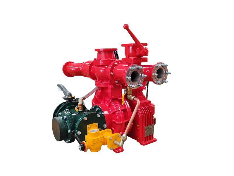
The ปั๊มดับเพลิงติดตั้งบนรถ CB10/60-RSประกอบด้วยปั๊มหอยโข่งแรงดันต่ำแบบขั้นเดียว ปั๊มสุญญากาศแบบลูกสูบคู่ อุปกรณ์ปลดคลัตช์แม่เหล็กไฟฟ้าอัตโนมัติ ชุดเพิ่มความเร็ว ท่อทางออกและวาล์วปิด-เปิด และท่อทางเข้า ♦ โครงสร้างหลักและหน้าที่การทำงาน (1) ปั๊มหอยโข่งแรงดันต่ำแบบขั้นเดียว:ประกอบด้วยฝาครอบปั๊ม ตัวเรือนปั๊ม ใบพัดขั้นแรก และเพลาปั๊ม ทำหน้าที่ให้แรงดันพิกัดและอัตราการไหลพิกัด (2) ชุดเพิ่มความเร็ว:ชุดเพิ่มความเร็วของปั๊มดับเพลิงติดตั้งบนรถ CB10/60-RS มีอัตราการเพิ่มความเร็วตามมาตรฐานที่ 1.440 (3) ปั๊มสุญญากาศแบบลูกสูบคู่:ประกอบด้วยลูกสูบ ตัวเรือนปั๊ม เพลาปั๊ม และล้อเยื้องศูนย์เป็นหลัก ล้อเยื้องศูนย์ติดตั้งร่วมกับก้านนำลูกสูบและปลอกเหล็กของตัวเรือนปั๊ม มีการติดตั้งวาล์วทางเข้าและทางออกที่ปลายทั้งสองด้านของปั๊มลูกสูบ เมื่อคลัตช์แม่เหล็กไฟฟ้าทำงาน ปั๊มลูกสูบจะเริ่มทำงาน ระหว่างการทำงาน การเคลื่อนที่เยื้องศูนย์ของล้อเยื้องศูนย์จะทำให้ลูกสูบเคลื่อนที่ไป-กลับ ค่อย ๆ ไล่อากาศออกจากปั๊มและท่อ ส่งผลให้สภาพอากาศดีขึ้น เกิดสุญญากาศภายในช่องปั๊มเพื่อให้บรรลุวัตถุประสงค์ในการดูดน้ำ 1. วาล์วปิด-เปิดทางออก (4 ชิ้น);2. ท่อน้ำทางออกด้านซ้ายและขวา;3. ข้อต่อน้ำกลับสำหรับระบายความร้อนของกระปุกเกียร์;4. ข้อต่อเกจวัดแรงดัน;5. เช็ควาล์วทางออก;6. หน้าแปลนปืนฉีดน้ำ;7. สวิตช์แรงดันน้ำ;8. ข้อต่อน้ำกลับแรงดันสำหรับระบายความร้อนของ PTO;9. หน้าแปลนถังน้ำด้านหลัง;10. บอลวาล์วถังน้ำด้านหลัง;11. กระปุกเกียร์;12. คลัตช์แม่เหล็กไฟฟ้าและสายไฟ;13. ปั๊มไพรเมอร์แบบลูกสูบ;14. ข้อต่อเกจสุญญากาศ;15. ข้อต่อไพรเมอร์สุญญากาศ;16. จุดเชื่อมต่อท่อทางเข้า;17. ท่อสี่ทางทางเข้า;18. วาล์วระบายน้ำของปั๊มน้ำ;19. ท่อน้ำกลับแรงดันสำหรับระบายความร้อนของกระปุกเกียร์;20. ท่อน้ำเข้าแรงดันสำหรับระบายความร้อนของกระปุกเกียร์;21. วาล์วระดับน้ำมันหล่อลื่นของกระปุกเกียร์;22. หน้าแปลนข้อต่อ;23. สายพานขับ;24. ข้อต่อเกลียวท่อน้ำแรงดันของเครื่องผสมโฟม (ไม่มีในรถบรรทุกน้ำ);25. จุดเชื่อมต่อเครื่องผสมโฟม;26. ข้อต่อน้ำทางออกแรงดันสำหรับระบายความร้อนของ PTO;27. ปั๊มดับเพลิงติดรถ CB10/60;28. ข้อต่อน้ำทางออกแรงดันสำหรับระบายความร้อนของกระปุกเกียร์;29. วาล์วผีเสื้อทางเข้าด้านหลัง (4) ท่อทางออกน้ำแรงดันต่ำและวาล์วปิด-เปิด: ประกอบด้วยเช็ควาล์วทางออกน้ำแรงดันต่ำ ท่อทางออกน้ำด้านซ้ายและขวา ท่อทางออกน้ำสี่ท่อ และวาล์วปิด-เปิดทางออกน้ำสี่ตัว (5) ท่อทางเข้าน้ำด้านหลัง: ประกอบด้วยท่อทางเข้าน้ำแบบสี่ทาง ตะแกรงกรองทางเข้า ข้อต่อทางเข้าภายนอก และที่ทั้งสองด้านของท่อทางเข้าน้ำแบบสี่ทาง ด้านขวามีช่องสำหรับติดตั้งเครื่องผสมโฟม ส่วนด้านซ้ายติดตั้งข้องอทางเข้าด้านหลังแบบหมุนได้ วาล์วผีเสื้อขนาด 150 มม. และหน้าแปลนสำหรับเชื่อม ♦ ข้อมูลจำเพาะ รุ่น เส้นผ่านศูนย์กลางทางเข้า (มม.) เส้นผ่านศูนย์กลางทางออก (มม.) สุญญากาศสูงสุด (kPa) ค่าการลดลงของสุญญากาศภายใน 1 นาที (MPa) เวลาสูบน้ำที่ความลึกดูด 7 ม. (วินาที) CB10/60-RS Φ150 Φ80X4 ≥85 ≤2.6 ≤50 รุ่น เงื่อนไขการทำงาน ความลึกในการดูด (ม.) อัตราการไหล (ลิตร/วินาที) แรงดัน (MPa) ความเร็วรอบเพลา (รอบ/นาที) กำลังเพลา (กิโลวัตต์) แรงดันใช้งานสูงสุด (MPa) CB10/60-RS 1 3 60 1.0 3200±50 99.71 1.082 2 42 1.3 3528+50 109.18 - 3 7 30 1.0 332650 - - ♦ การใช้งาน 1. งานเตรียมการก่อนการใช้งาน (1) ต้องปิดวาล์วระบายน้ำทั้งหมดบนปั๊ม (2) สำหรับรถดับเพลิงโฟม ต้องปิดบอลวาล์วท่อส่งโฟมและเครื่องผสมโฟม (3) สำหร...
รายละเอียด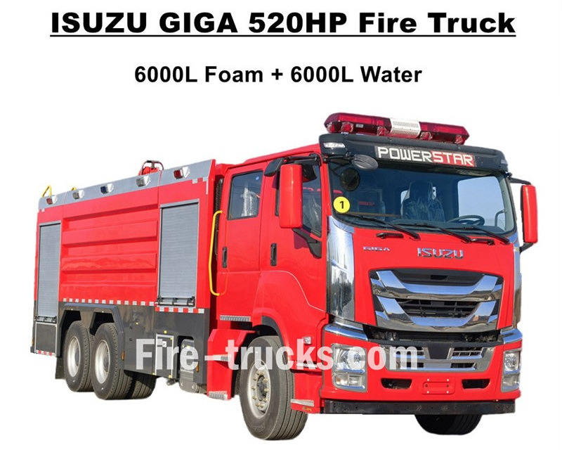
คุณภาพสูงสุดรถดับเพลิง ISUZU GIGAส่งออกไปยังแอฟริกาตะวันตก บูร์กินาฟาโซ ซึ่งออกแบบโดยใช้แชสซีรถบรรทุกงานหนัก ISUZU GIGA VC66 6x4 ติดตั้งห้องโดยสารใหม่ GIGA VC66 เบาะนั่งระบบกันสะเทือนอากาศมาตรฐานและเครื่องปรับอากาศเพื่อการขับขี่ที่สะดวกสบาย รถติดตั้งเครื่องยนต์ดีเซลเทคโนโลยีญี่ปุ่น ISUZU รุ่น 6WG1-TCG62 กำลัง 520HP และความจุกระบอกสูบ 15681cc ทำงานร่วมกับเกียร์ธรรมดา FAST 12 สปีด มีอัตราการสิ้นเปลืองเชื้อเพลิงต่ำมาก มาตรฐานยางหน้า 385/80R22.5 และยางหลัง 315/80R22.5 รวมทั้งหมด 10+1 คัน ชุดอุปกรณ์ส่วนบนประกอบด้วยถังน้ำ 6000L และถังโฟม 6000L ผลิตจากวัสดุสแตนเลส #304 ทั้งหมด ทนทานสำหรับการใช้งานยาวนาน ทำงานร่วมกับปั๊มดับเพลิงกำลังสูงพิเศษ CB10/140 แบบสั่งทำพิเศษ มีอัตราการไหลอย่างมีประสิทธิภาพ 140L/s ติดตั้งร่วมกับปืนฉีดน้ำดับเพลิงคู่ด้านบนชุดตัวถังถังบรรจุ รุ่น PL8/64 และมีอัตราการไหลอย่างมีประสิทธิภาพ 64L/sรถดับเพลิง ISUZU GIGA 520HPติดตั้งอุปกรณ์ดับเพลิงที่จำเป็นครบชุด เป็นรถดับเพลิงที่เหมาะสำหรับการดับไฟและช่วยเหลือผู้คน และมีการใช้งานอย่างแพร่หลายในตลาดบูร์กินาฟาโซ รถดับเพลิงถังโฟม ISUZU GIGA 520HP ขนาด 14,000L โรงงาน CS TRUCKS เป็นผู้ผลิตมืออาชีพในด้านรถบรรทุกรับประกันว่าสินค้าทั้งหมดเป็นของใหม่และมีคุณภาพสูง คุณสมบัติรถดับเพลิง ISUZU: ชื่อ ร�
รายละเอียด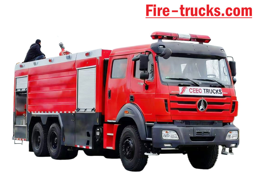
ไบเบน รถดับเพลิงคันนี้สร้างขึ้นบนแชสซีและตัวถังแบบ Beiben รุ่น 2638 Type II 6*4 พวงมาลัยซ้าย ความจุอาจสูงถึง 12,000 ลิตร โดยประกอบด้วยถังเก็บน้ำขนาด 10,000 ลิตร และถังบรรจุโฟมขนาด 2,000 ลิตร หน่วยกู้ภัยดับเพลิง Beiben 2638 รถบรรทุก ติดตั้งปั๊มดับเพลิง XIONGZHEN CB10/60 และหัวฉีดดับเพลิง PL8/48 สะดวกมากสำหรับ ใช้งานประจำวัน ส่วนใหญ่ใช้สำหรับโครงการดับเพลิงในพื้นที่ที่ต้องการความช่วยเหลือ รถคันนี้ได้รับการออกแบบโดยอาศัยข้อดีของแชสซีรถบรรทุกยี่ห้อ Beiben รุ่นดั้งเดิมอย่างเต็มที่ คำนึงถึงความสะดวกสบายและความน่าเชื่อถือของผลิตภัณฑ์อย่างครบถ้วน รวมถึงตัวถังที่ออกแบบใหม่ด้วย วัสดุที่ใช้คือเหล็กกล้าคาร์บอนมาตรฐานสากลเคลือบสีป้องกันการกัดกร่อนและเหล็กกล้าไร้สนิม ซึ่ง สามารถป้องกันการเกิดสนิมได้อย่างมีประสิทธิภาพและช่วยยืดอายุการใช้งานให้ยาวนานขึ้น รถดับเพลิง Beiben 6x4 พร้อมอุปกรณ์ครบครัน ได้แก่ ระบบส่งกำลังแบบ Sandwich PTO, ปั๊มดับเพลิง, หัวฉีดน้ำดับเพลิง, ห้องพักเจ้าหน้าที่ และสายฉีดน้ำ กล่อง, ห้องปั๊ม, รถบรรทุกผงแห้ง และระบบไนโตรเจน พร้อมม้วนสายยางสำหรับท่อส่ง (ภาษาอังกฤษ) กล่องควบคุมเวอร์ชัน ท่อทางเข้าและทางออก บันไดปีนด้านหลัง โคมไฟหมอนด้านบน และอุปกรณ์ที่จำเป็นทั้งหมด อุปกรณ์ดับเพลิง ห้องโดยสาร�
รายละเอียด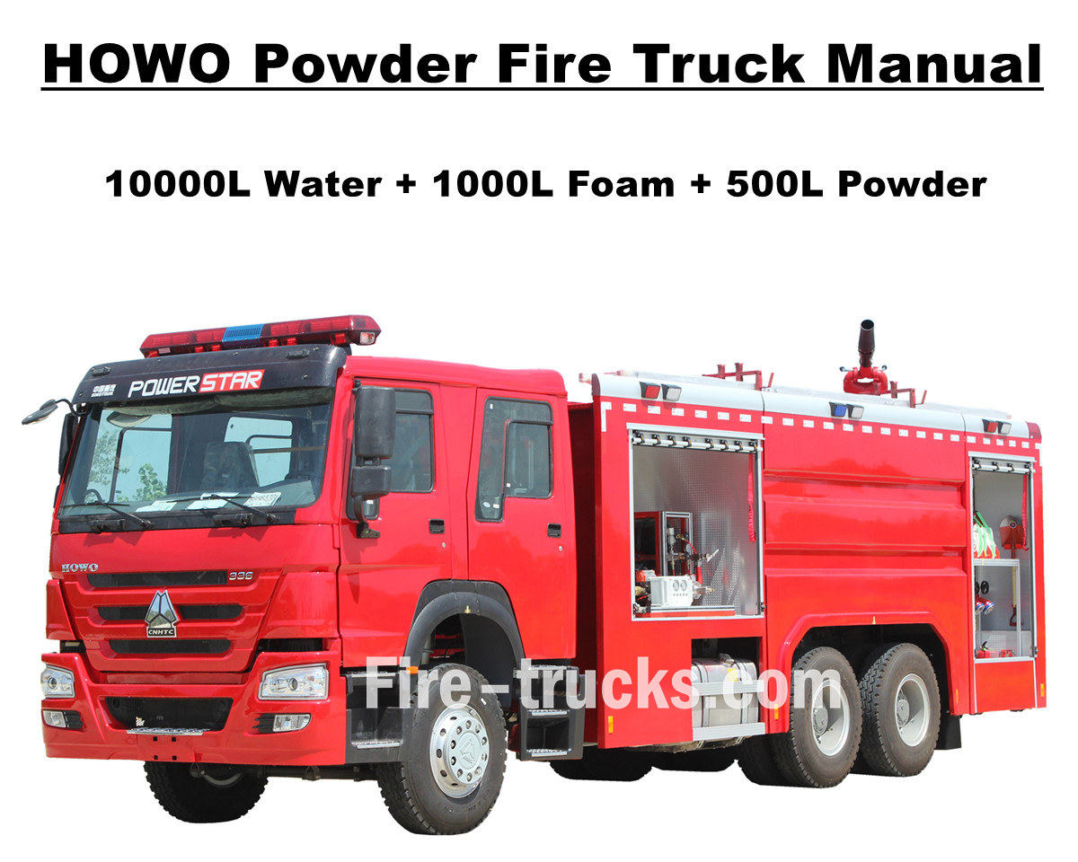
ลูกค้าจากประเทศมอริเตเนีย ทวีปแอฟริกา ซื้อสินค้าทั้งหมด 4 ชิ้น รถดับเพลิงแบบปั๊ม Sinotruk HOWO จาก POWERSTAR TRUCKS และใช้งานในเมืองหลวงนูอากชอต รถดับเพลิง หรือเรียกอีกอย่างว่ารถดับเพลิงแบบสูบน้ำ เป็นยานพาหนะที่ออกแบบและผลิตขึ้นเพื่อตอบสนองความต้องการของโครงการดับเพลิงและช่วยเหลือผู้คนหลากหลายรูปแบบในระดับสากล มีห้องโดยสารสองแถวที่ปรับแต่งมาเป็นพิเศษสำหรับการบรรทุกนักดับเพลิง อุปกรณ์และเครื่องมือดับเพลิงต่างๆ สำหรับการดับเพลิงและกู้ภัย เพื่อรับประกันว่ารถดับเพลิง HOWO ทำงานได้อย่างมีประสิทธิภาพมากขึ้น เราได้ปรับแต่งให้รถติดตั้งบันไดอลูมิเนียมอัลลอยด์ สารดับเพลิงแบบน้ำ โฟม และผงแห้ง และถังเก็บ ปั๊มดับเพลิงรุ่น CB10/60 ที่มีประสิทธิภาพสูง จับคู่กับหัวฉีดดับเพลิง PL8/48 ที่มีระยะการฉีดน้ำมากกว่า 70 เมตร สายฉีดน้ำดับเพลิงพร้อมปืนสำหรับดับเพลิงระยะไกล อุปกรณ์ช่วยหายใจพร้อมหน้ากาก ชุดป้องกัน เครื่องมือช่วยเหลือ ชุดปฐมพยาบาล ฯลฯ บริการทั้งหมดนี้สำหรับรถดับเพลิง HOWO เพื่อให้การทำงานมีประสิทธิภาพและเชื่อถือได้ เพื่อให้มั่นใจว่าลูกค้าในมอริเตเนียสามารถใช้งานรถดับเพลิง HOWO ได้ง่ายและมีประสิทธิภาพยิ่งขึ้น รถทุกคันจึงมาพร้อมกับแคตตาล็อกบริการฉบับภาษาอังกฤษครบชุด
รายละเอียด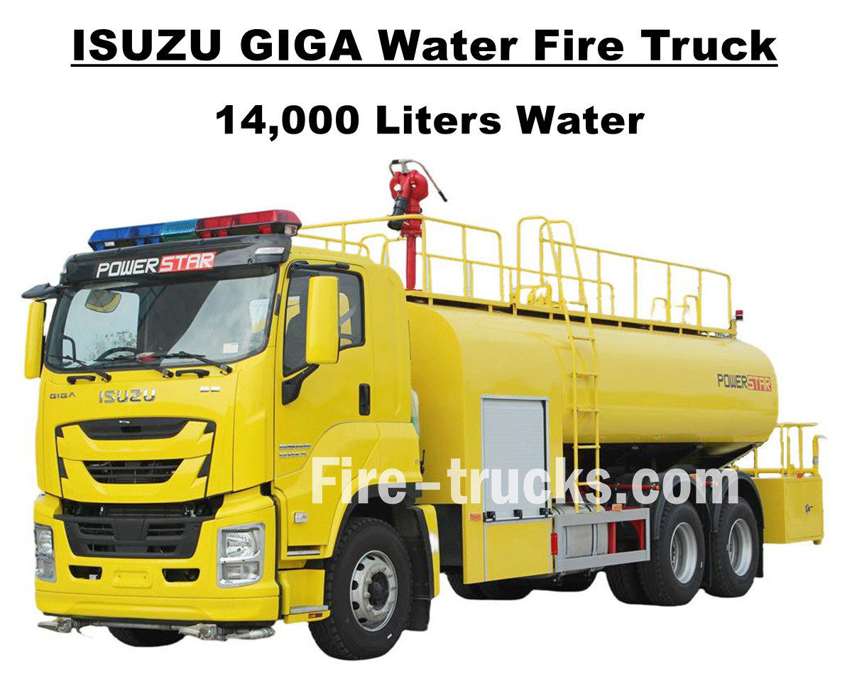
นายโจเซฟ ลูกค้าจากฮอนดูรัส ซึ่งเป็นลูกค้าในอเมริกาใต้ ได้ซื้อไป 1 เครื่อง รถบรรทุกน้ำดับเพลิง Isuzu GIGA VC66 ขนาด 14000 ลิตร (3700 แกลลอน) จาก POWERSTAR TRUCKS ซึ่งออกแบบโดยใช้แชสซีรถบรรทุกหนัก ISUZU GIGA 6x4 ของญี่ปุ่น ติดตั้งเครื่องยนต์ดีเซลรุ่น 6UZ1-TCG60 กำลัง 280 กิโลวัตต์ / 380 แรงม้า เป็นเครื่องยนต์ 6 สูบ 4 จังหวะ ระบายความร้อนด้วยน้ำ เทอร์โบชาร์จและอินเตอร์คูลเลอร์ ปริมาตรกระบอกสูบ 9839 มล. จับคู่กับเกียร์ธรรมดา FAST 12 มาตรฐานสากล 12 เกียร์เดินหน้าและ 2 เกียร์ถอยหลัง ช่วยลดการสิ้นเปลืองเชื้อเพลิงได้อย่างมีประสิทธิภาพ ติดตั้งล้อเหล็ก 13 ล้อ รุ่น 12R22.5 รวมถึงล้ออะไหล่ 1 ล้อ เหมาะสำหรับสภาพถนนหลากหลายประเภทและเหมาะสำหรับการปีนเขา ระยะฐานล้อสามารถเลือกได้หลายแบบ 4600+1370 มม. บริการที่ออกแบบมาอย่างเหมาะสมและสะดวกสบายสำหรับโครงการดับเพลิงในหลายพื้นที่ รถดับเพลิงบรรทุกน้ำ Isuzu GIGA ขนาด 3700 แกลลอน ใช้แชสซีรถบรรทุก ISUZU เทคโนโลยีจากญี่ปุ่นอย่างเต็มรูปแบบ ห้องโดยสาร GIGA VC66 แท้ พร้อมระบบปรับอากาศที่มีทั้งฟังก์ชั่นทำความร้อนและทำความเย็นเพื่อความสะดวกสบายในการขับขี่ ตัวถังบรรทุกน้ำทำจากสแตนเลส SS304 ความจุ 14000 ลิตร หรือ 3700 แกลลอน ติดตั้งปั๊มดับเพลิงยี่ห้อจีน CB10/60 และหัวฉีดดับเพลิง PS8/50 บนตัวถัง พร้อมอุปกรณ์ดับเพลิงและกู้ภัยครบชุด และพ่นสีเหลืองมะนาวแบบพิเศษทั้งคัน ทำให้รถคันนี้เป็นยานพาหนะที่เหมาะสมอย่างยิ่งสำหรับโครงการดับเพลิงบนท้องถนนและชุมชนในประเทศฮอนดูรัส นอกจากนี้ รถยังมาพร้อมกับแคตตาล็อกภาษาอังกฤษครบชุดสำหรับการใช้งาน รวมถึงคู่มือการใช้งาน คู่มือรถ GIGA และคู่มืออะไหล่สำหรับการบำรุงรักษา รถดับเพลิง Isuzu GIGA สูบน้ำขนาด 14,000 ลิตร โรงงานพาวเวอร์สตาร์ เป็นผู้ผลิตมืออาชีพในด้านรถบรรทุก รับประกันว่าสินค้าทุกชิ้นเป็นของใหม่และมีคุณภาพสูง - Ⅰ. ข้อดีของรถดับเพลิงน้ำอีซูซุ : ★ เครื่องยนต์ดีเซล 6WG1 กำลัง 280KW / 380HP ทรงพลัง ใช้งานได้ 100,000 กม. โดยไม่มีปัญหา ★ ISUZU VC66 ห้องโดยสาร GIGA ใหม่ล่าสุด ดีไซน์สไตล์ยุโรป ★ ปั๊มดับเพลิงแบบติดตั้ง CB10/60 อัตราการไหล 60 ลิตร/วินาที เชื่อถือได้สูง ★ ปืนฉีดน้ำแรงดันสูง PS8/50 ติดตั้งด้านบน ทนทานใช้งานได้นาน ★ ระบบควบคุมแบบบูรณาการ พร้อมแผงควบคุมด้านข้าง ★ สีเหลืองมะนาวแบบสั่งทำพิเศษ สวยงามและสดใส ปั๊มดับเพลิง CB10/60 แบบอย่าง - ซีบี10/60 ความดัน - 1.0 MPa แรงดันใช้งานสูงสุด - 1.232 เมกะปาสคาล อัตราการไหล - อัตราการไหล 60 ลิตร/วินาที ที่ 1.0 MPa ความเร็วรอบ 3286±50 รอบ/นาที กำลังไฟฟ้า 102 กิโลวัตต์ ความลึกในการดูด 3 เมตร อัตราการไหล 42 ลิตร/วินาที ที่ 1.3 MPa ความเร็วรอบ 3519±50 รอบ/นาที กำลังไฟฟ้า 106 กิโลวัตต์ ความลึกในการดูด 3 เมตร อัตราการไหล 30 ลิตร/วินาที ที่ 1.0 MPa ความเร็วรอบ 3120±50 รอบ/นาที กำลังไฟฟ้า 73 กิโลวัตต์ ความลึกในการดูด 7 เมตร อัตราทดความเร็ว - 1:1.44 เครื่องตรวจวัดไฟ PS8/50 แบบอย่าง - PS8/50 ความดัน - 0.8 เมกะปาสคาล ช่วงการทำงาน - น้ำ ≥ 65 ม การหมุนแนวตั้ง - -45° ถึง +70° การหมุนแนวนอน - 0° ~ 360° อัตราการไหล - 50 ลิตร/วินาที - Ⅱ - ภาพวาดรถดับเพลิงอีซูซุ: รถดับเพลิงบรรทุกน้ำ ISUZU GIGA VC66 ขนาด 14000 ลิตร ออกแบบและส่งออกไปยังประเทศฮอนดูรัสในทวีปอเมริกาใต้ ตัวรถติดตั้งถังน้ำขนาด 3700 แกลลอน ผลิตจากสแตนเลส SS304 หนา 5 มม. ด้านหลังมีแท่นวางเครื่องมือและกล่องเครื่องมือขนาดเล็ก ระหว่างห้องโดยสาร GIGA กับถังน้ำมีห้องปั๊มน้ำพร้อมปั๊มน้ำ CB10/60 ติดตั้งปืนฉีดน้ำดับเพลิง P...
รายละเอียด
บริษัท Powerstar Trucks ผลิตรถยนต์สำหรับภารกิจฉุกเฉินแบบสั่งทำพิเศษ และ รถดับเพลิง เป็นเวลาหลายปีที่ Powerstar Trucks Emergency Response ได้สร้างชื่อเสียงในฐานะผู้ผลิตรถดับเพลิงแบบสั่งทำพิเศษครบวงจรชั้นนำ ด้วยความเชี่ยวชาญในด้านต่างๆ รถดับเพลิงฉีดโฟม และ รถดับเพลิงกู้ภัย ด้วยรากฐานจากมรดกที่นักดับเพลิงไว้วางใจ รถดับเพลิง Powerstar นำเสนอโซลูชันที่ยืดหยุ่น มีกลยุทธ์ และเชี่ยวชาญเฉพาะด้าน เพื่อตอบสนองความต้องการเฉพาะของหน่วยดับเพลิงแต่ละแห่ง โดยให้ความสำคัญกับผู้ตอบสนองเหตุฉุกเฉินเป็นอันดับแรก รถดับเพลิงกู้ภัย 120 คัน สำหรับส่งมอบ ส่งออกรถดับเพลิงกู้ภัย 65 คัน ให้แก่ตำรวจยูกันดา รถดับเพลิงน้ำ รถดับเพลิงโฟม โดยหลักแล้ว รถดับเพลิงแบ่งออกเป็น 4 ประเภทตามหน้าที่การใช้งาน ได้แก่ รถดับเพลิงทั่วไป รถบันไดดับเพลิง รถดับเพลิงใช้งานเฉพาะทาง และรถดับเพลิงสนับสนุนด้านโลจิสติกส์ 01, รถดับเพลิง เป็นกำลังหลักในการดับเพลิงโดยตรง ซึ่งรวมถึง: * **รถดับเพลิงแบบมีถังน้ำ:** มาพร้อมถังน้ำและปั๊มน้ำ เหมาะสำหรับการดับเพลิงทั่วไป * **รถดับเพลิงชนิดโฟม:** ออกแบบมาโดยเฉพาะสำหรับดับเพลิงที่เกิดจากของเหลวไวไฟ เช่น น้ำมัน * **รถดับเพลิงชนิดผงแห้ง:** เหมาะสำหรับดับเพลิงที่เกิดจากแก๊สและไฟฟ้า * **รถดับเพลิงคาร์บอนไ
รายละเอียด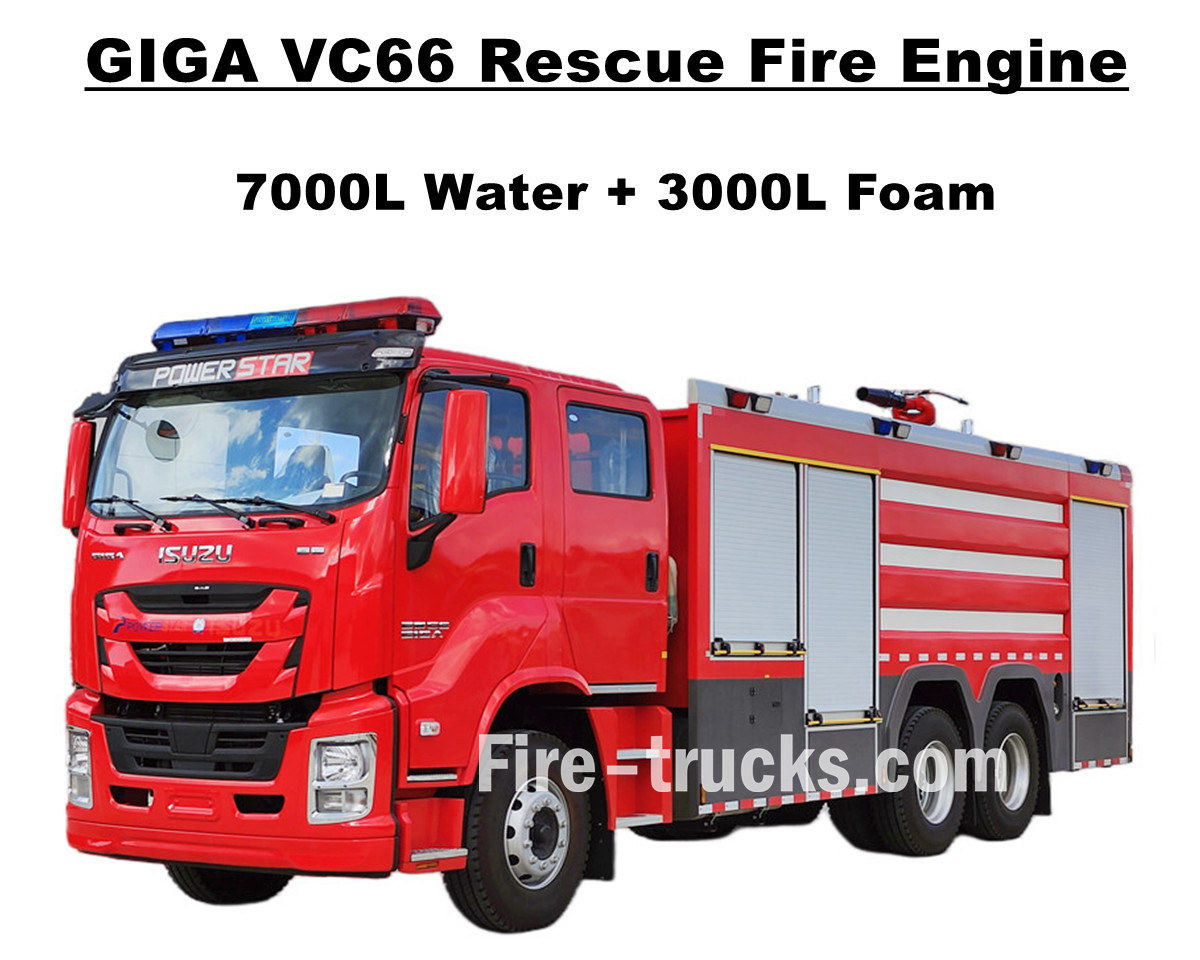
ลูกค้าในกรุงมะนิลา ประเทศฟิลิปปินส์ ได้ซื้อสินค้าแล้ว รถดับเพลิงสำหรับงานหนัก Isuzu GIGA VC66 จาก POWERSTAR TRUCKS ซึ่งติดตั้งเครื่องยนต์ดีเซล ISUZU ของญี่ปุ่น รุ่น 6WG1-TCG61 กำลัง 338 กิโลวัตต์ / 460 แรงม้า เป็นเครื่องยนต์ 6 สูบ 4 จังหวะ ระบายความร้อนด้วยน้ำ เทอร์โบชาร์จ และอินเตอร์คูลเลอร์ ขนาดความจุมาตรฐาน 15681 ซีซี จับคู่กับเกียร์ธรรมดา FAST 12 จังหวะ มาตรฐานสากล 12 เกียร์เดินหน้าและ 2 เกียร์ถอยหลัง ประหยัดน้ำมันมาก ติดตั้งยางแบบไม่ใช้ยางในทั้งหมด 13 เส้น ขนาด 315/80R22.5 รวมถึงยางอะไหล่ 1 เส้น เหมาะสำหรับสภาพถนนหลากหลายประเภท และให้บริการสำหรับโครงการดับเพลิงในหลายพื้นที่ รถบรรทุก ISUZU GIGA VC66 ดั้งเดิมได้รับการดัดแปลงเป็นห้องโดยสารสองแถวของ GIGA โดยมีที่นั่งปกติ 2+1 ที่นั่งด้านหน้าและที่นั่ง SCBA 4 ที่นั่งด้านหลัง ภายในห้องโดยสารติดตั้งเครื่องปรับอากาศพร้อมฟังก์ชั่นทำความร้อนและทำความเย็นเพื่อการขับขี่ที่สะดวกสบาย ตัวรถติดตั้งถังน้ำดับเพลิงทำจากสแตนเลส SS304 ทั้งหมด ติดตั้งปั๊มดับเพลิง XIONGZHEN CB10/60 ยี่ห้อดังจากจีนที่ห้องปั๊มด้านหลัง ทำงานร่วมกับหัวฉีดน้ำดับเพลิง WESTER PL8/48 ที่ด้านบนของถังน้ำ พร้อมอุปกรณ์ดับเพลิงและกู้ภัยครบชุด ทำให้รถคันนี้เป็นยานพาหนะที่เหมาะสมอย่างยิ่งสำหรับโครงการดับเพลิงบนท้องถนนและชุมชนในกรุงเทพฯ นอกจากนี้ รถยังมาพร้อมกับแคตตาล็อกภาษาอังกฤษครบชุดสำหรับการใช้งาน รวมถึงคู่มือการใช้งาน คู่มือรถ GIGA และคู่มืออะไหล่สำหรับการบำรุงรักษา รถดับเพลิงอีซูซุ ความจุ 7,000 ลิตร น้ำ 3,000 ลิตร โฟม โรงงานพาวเวอร์สตาร์ เป็นผู้ผลิตมืออาชีพในด้านรถบรรทุก รับประกันว่าสินค้าทุกชิ้นเป็นของใหม่และมีคุณภาพสูง - Ⅰ. คุณสมบัติหลักของรถดับเพลิง Isuzu 6WG1 : ★ เครื่องยนต์ดีเซล 6WG1 กำลัง 338KW / 460HP อันทรงพลัง ใช้งานได้ 100,000 กม. โดยไม่มีปัญหา ★ ISUZU VC66 ห้องโดยสาร GIGA ใหม่ล่าสุด ดีไซน์สไตล์ยุโรป ★ ห้องโดยสารแบบสองแถว พร้อมที่นั่ง SCBA 4 ที่นั่งด้านหลัง ★ ปั๊มดับเพลิงแบบติดตั้ง CB10/60-XZ อัตราการไหล 60 ลิตร/วินาที เชื่อถือได้สูง ★ ปืนฉีดโฟมดับเพลิง PL8/48 ติดตั้งด้านบน ทนทานต่อการใช้งาน ★ ระบบควบคุมแบบบูรณาการ พร้อมแผงควบคุมด้านหลัง ปั๊มดับเพลิง CB10/60-XZ แบบอย่าง - ซีบี10/60-XZ ความดัน - 1.0 MPa แรงดันใช้งานสูงสุด - 1.232 เมกะปาสคาล อัตราการไหล - อัตราการไหล 60 ลิตร/วินาที ที่ 1.0 MPa ความเร็วรอบ 3286±50 รอบ/นาที กำลังไฟฟ้า 102 กิโลวัตต์ ความลึกในการดูด 3 เมตร อัตราการไหล 42 ลิตร/วินาที ที่ 1.3 MPa ความเร็วรอบ 3519±50 รอบ/นาที กำลังไฟฟ้า 106 กิโลวัตต์ ความลึกในการดูด 3 เมตร อัตราการไหล 30 ลิตร/วินาที ที่ 1.0 MPa ความเร็วรอบ 3120±50 รอบ/นาที กำลังไฟฟ้า 73 กิโลวัตต์ ความลึกในการดูด 7 เมตร อัตราทดความเร็ว - 1:1.44 เครื่องตรวจสอบเพลิงไหม้ PL8/48 แบบอย่าง - PL8/48 ความดัน - 0.8 เมกะปาสคาล ช่วงการทำงาน - โฟม ≥ 70 ม. และน้ำ ≥ 60 เมตร การหมุนแนวตั้ง - -45° ถึง +70° การหมุนแนวนอน - 0° ~ 360° อัตราการไหล - 48 ลิตร/วินาที - Ⅱ - ภาพวาดทางเทคนิคของรถดับเพลิงกู้ภัยอีซูซุ: รถดับเพลิง ISUZU GIGA VC66 ติดตั้งถังน้ำและถังโฟม จับคู่กับหัวฉีดดับเพลิง XIONGZHEN CB10/60 และหัวฉีดดับเพลิง Wester PL8/48 ซึ่งเป็นรถดับเพลิงที่เหมาะสมอย่างยิ่งสำหรับบริการกู้ภัยดับเพลิงในกรุงมะนิลา ประเทศฟิลิปปินส์ - Ⅲ ภาพรวมรถดับเพลิง GIGA: รถดับเพลิงรุ่นใหม่ ISUZU GIGA VC66 เป็นรถกู้ภัยดับเพลิงและช่วยเหลือผู้คนในอุดมคติ มีคุณสมบัติการออกแบบที่ล้ำสมัยและคุณภาพที่เชื่อ...
รายละเอียด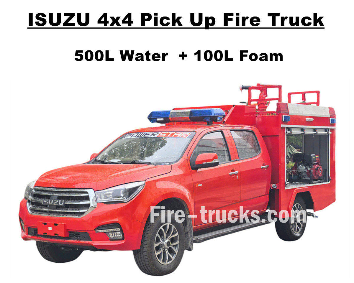
ขายตรงจากโรงงาน รถกระบะ ISUZU 4x4 ออฟโรดสำหรับดับเพลิง รถดับเพลิงอิซูซูกิ 143 แรงม้าคันนี้ ใช้แชสซีขับเคลื่อนสี่ล้อ ISUZU TAGA ผสานระบบกำลังที่ยอดเยี่ยมเพื่อรับมือกับสภาพถนนที่ยากลำบากทุกประเภท ตัวรถติดตั้งชุดถังน้ำสแตนเลส SS304 ทั้งหมด รวมถึงถังน้ำขนาด 500 ลิตร และถังโฟมขนาด 100 ลิตร พร้อมปั๊มดับเพลิงแบบอิสระระดับมืออาชีพ JBQ4.5/9 ติดตั้งที่ห้องปั๊มด้านหลัง มีระยะการฉีดพ่นไกล และมีแผงควบคุมภาษาต่างๆ ให้เลือก นอกจากนี้ยังมีตัวเลือกการกำหนดค่าต่างๆ เพื่อตอบสนองความต้องการที่แตกต่างกัน และติดตั้งหัวฉีดน้ำดับเพลิง PS20 ไว้ด้านบน รถดับเพลิงอิซูซูกิ 143 แรงม้าคันนี้ ให้การรับประกันความปลอดภัยจากอัคคีภัยอย่างมั่นคง และแสดงให้เห็นถึงประสิทธิภาพและความยืดหยุ่นที่ยอดเยี่ยม ห้องโดยสารแบบสองแถวของรถดับเพลิงอิซูซูกิให้พื้นที่และคุณภาพที่เพียงพอสำหรับการบรรทุกอุปกรณ์ดับเพลิงและรักษาประสิทธิภาพการขับขี่ที่ดี ห้องโดยสารสามารถรองรับนักดับเพลิงได้ 5 คน และติดตั้งเครื่องปรับอากาศเพื่อให้ผู้ขับขี่รู้สึกสบายในทุกสภาพอากาศ ทั้งหมดนี้รับประกันได้ว่ารถดับเพลิงโฟมอิซูซูกิ 600 ลิตรคันนี้จะเป็นรถกู้ภัยดับเพลิงที่เหมาะสมอย่างยิ่งสำหรับตลาดแอลเบเนีย และด้านล่างนี้คือคู่มือผู้ใช้ที่ระบุถึงวิธีการใช้งานและความปลอดภัยในการทำงาน - Ⅰ. คุณสมบัติหลักของรถกระบะดับเพลิง Isuzu : ★ เครื่องยนต์ 4KH1 กำลัง 105KW / 143HP อันทรงพลัง ใช้งานได้ 100,000 กม. โดยไม่มีปัญหา ★ ห้องโดยสารกระบะ ISUZU TAGA รุ่นใหม่ล่าสุด ดีไซน์สไตล์ยุโรป ★ ห้องโดยสารคู่แบบดั้งเดิม เหมาะสำหรับนักดับเพลิง 5 นาย ★ ปั๊มดับเพลิง JBQ4.5/9 แบบอิสระ เชื่อถือได้สูง ★ ปืนใหญ่ยิงกระสุน PS8/20 ติดตั้งด้านบน ทนทานใช้งานได้นาน - Ⅱ. ภาพรวมการรับรถดับเพลิง: รถดับเพลิง ISUZU 4x4 ออฟโรด AWD ระบบน้ำและโฟม เป็นรถดับเพลิงกู้ภัยอเนกประสงค์ที่ให้บริการในหลายพื้นที่ รวมถึงชุมชน ป่าไม้ โรงงาน ฯลฯ ด้วยความสามารถในการขับขี่บนทางวิบากและรูปลักษณ์ที่เพรียวบาง รถดับเพลิง Isuzu Pickup คันนี้จึงสามารถปฏิบัติภารกิจได้หลากหลาย และเพื่อให้รถดับเพลิงของเราเหมาะสมกับลูกค้าแต่ละรายมากยิ่งขึ้น ด้านล่างนี้คือตัวเลือกต่างๆ สำหรับลูกค้าที่แตกต่างกัน - วัสดุสำหรับรถบรรทุกน้ำมัน - เหล็กกล้าคาร์บอน, เหล็กกล้าไร้สนิม, โลหะผสมอลูมิเนียม, วัสดุ PP - เครื่องสูบน้ำดับเพลิง - ขึ้นอยู่กับตัวถังของเรือบรรทุกน้ำมันและระยะการพ่นสารเคมี (ตัวเลือกเสริมจากอเมริกา) ดาร์ลีย์ ยี่ห้อ - ไม่จำเป็น: ท่อ, ม้วนสายยาง, บันไดอลูมิเนียม, ข้อต่อ (แบบจีน, ยุโรป, อเมริกา) - Ⅲ. รูปลักษณ์ที่ดึงดูดใจ: รถดับเพลิงแบบกระบะขับเคลื่อนสี่ล้อ ISUZU 4x4 AWD มีกำลังและตอบสนองได้ดี สามารถเข้าถึงที่เกิดเหตุได้อย่างรวดเร็ว และสามารถผ่านภูมิประเทศที่ซับซ้อนได้อย่างง่ายดาย ปืนฉีดน้ำดับเพลิงด้านบนมีระยะฉีดไกลและอัตราการไหลสูง และสายฉีดน้ำดับเพลิงยาว 50 เมตรพร้อมปืนฉีดน้ำสามารถฉีดไปยังแหล่งกำเนิดไฟได้อย่างแม่นยำ และครอบคลุมและแยกพื้นที่ได้อย่างมีประสิทธิภาพ นอกจากนี้ รถดับเพลิงแบบกระบะยังติดตั้งอุปกรณ์กู้ภัยครบชุด สำหรับสถานการณ์ไฟไหม้ที่แตกต่างกัน เช่น อาคาร ป่าไม้ ถังน้ำมัน และการรั่วไหลของสารเคมีอันตราย สามารถปรับกลยุทธ์ได้ตามสถานการณ์ ไม่ว่าจะเป็นการต่อสู้แบบรวดเร็วหรือการโจมตีแบบแม่นยำ และรถดับเพลิงกู้ภัยแบบกระบะ Isuzu ประเภทนี้มีประสิทธิภาพดีและได้รับการบริการอย่างน่าเชื่อถือในประเทศแอลเบเนีย รถกระบะ Isuzu 4x4 ห้องโดยสารขับขี่สะดวกสบายของรถกระบะอีซูซุ คู่มือการใช้งานและแคตตาล็อกชิ้นส่วนรถดับเพลิงอีซ...
รายละเอียด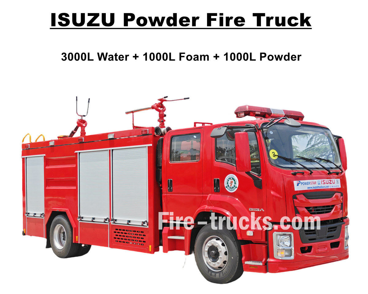
ออกแบบและผลิตใหม่ รถดับเพลิงชนิดผงแห้งและน้ำ ISUZU GIGA 4X รถดับเพลิง ISUZU สมรรถนะสูงคันนี้ส่งออกไปยังเมืองลากอส ประเทศไนจีเรีย ติดตั้งเครื่องยนต์ดีเซล 4HK1-TCG60 ขนาด 5193 ซีซี กำลัง 150 กิโลวัตต์/205 แรงม้า จับคู่กับเกียร์ธรรมดา MLD 6 จังหวะ เดินหน้า 6 จังหวะ ถอยหลัง 1 จังหวะ ให้กำลังขับอย่างมีประสิทธิภาพ ประหยัดน้ำมัน ตอบสนองรวดเร็ว และขับขี่ได้อย่างมั่นคง รถดับเพลิง Isuzu 5000 ลิตร มาพร้อมชุดถังบรรจุน้ำขนาด 5000 ลิตร ประกอบด้วยถังน้ำ 3000 ลิตร ถังโฟม 1000 ลิตร และถังผงดับเพลิง 1000 ลิตร ถังทุกใบทำจากสแตนเลส SS304 รูปทรงสี่เหลี่ยม มีแผ่นกั้นภายใน ฝาปิดเป็นแบบ DN500 พร้อมตัวล็อคเพื่อความปลอดภัย รถดับเพลิงอิซูซุรุ่น Giga 4X ติดตั้งปั๊มดับเพลิง CB10/40 ที่มีอัตราการไหล 40 ลิตร/วินาที ทำงานร่วมกับหัวฉีดน้ำผสมโฟมดับเพลิง PL8/32 ที่มีอัตราการไหล 32 ลิตร/วินาที พร้อมอุปกรณ์กู้ภัยดับเพลิงหลากหลายชนิด ทำให้รถดับเพลิง ISUZU Giga 4X เป็นรถที่เหมาะสมอย่างยิ่งสำหรับการดับเพลิงและกู้ภัยผู้คน และทำงานได้อย่างมีประสิทธิภาพในประเทศไนจีเรีย เมืองลากอส นอกจากนี้ รถคันนี้ยังติดตั้งรถบรรทุกน้ำดับเพลิงชนิดผงแห้ง รุ่น R25-006 ที่มีแรงดัน 1.55 MPa และปริมาตร 1,000 ลิตร พร้อมถังไนโตรเจนสำหรับใช้งาน และเพื่อรับประกันการทำงานและประสิทธิภาพของรถดับเพลิงอิซูซุให้ดียิ่งขึ้น คู่มือการใช้งานที่แนบมาด้านล่างนี้เป็นแนวทางสำหรับลูกค้าในไนจีเรีย ♦ รถดับเพลิงแบบใช้ผงแห้ง ISUZU GIGA ♦ คู่มือการใช้งานรถดับเพลิงผงแห้ง POWERSTAR ISUZU สำหรับส่งออกไปยังไนจีเรีย แผงควบคุมรถดับเพลิง ISUZU รายละเอียดชิ้นส่วนรถดับเพลิงกู้ภัย ISUZU - Ⅰ. คุณสมบัติหลักของรถดับเพลิงอีซูซุ : ★ เครื่องยนต์ 4HK1 ทรงพลัง 205 แรงม้า วิ่ง 100,000 กม. โดยไม่มีปัญหา ★ ISUZU GIGA รุ่นใหม่ ห้องโดยสาร 4X ดีไซน์แบบยุโรป ★ เพลาเทคโนโลยี ISUZU เหมาะอย่างยิ่งสำหรับแอฟริกา ★ ปั๊ม CB10/40 ชื่อดังจากจีน เชื่อถือได้สุดๆ ★ ปืนใหญ่ยิงไฟ PL8/32 ดีไซน์ยอดเยี่ยม ทนทาน ★ ชุดผงแห้ง พร้อมขวดไนโตรเจนที่เข้าชุดกัน - Ⅱ. ผู้ผลิตรถดับเพลิง ISUZU: รถดับเพลิง ISUZU GIGA ชนิดน้ำ โฟม และผงแห้ง เป็นรถดับเพลิงขนาดกลางที่ใช้งานได้เต็มรูปแบบ ผสานรวมความคล่องตัวสูง ปริมาณสารดับเพลิงสำรองที่เพียงพอ และความสามารถในการต่อสู้ที่หลากหลาย ในด้านกำลังขับเคลื่อน ใช้เครื่องยนต์ Weichai จับคู่กับระบบส่งกำลัง Sinotruk ให้กำลังที่แข็งแกร่งและการส่งกำลังที่มีประสิทธิภาพ - วัสดุสำหรับรถบรรทุกน้ำมัน - เหล็กกล้าคาร์บอน, เหล็กกล้าไร้สนิม, โลหะผสมอลูมิเนียม, วัสดุ PP - เครื่องสูบน้ำดับเพลิง - ขึ้นอยู่กับตัวถังของเรือบรรทุกน้ำมันและระยะการพ่นสารเคมี (ตัวเลือกเสริมจากอเมริกา) ดาร์ลีย์ ยี่ห้อ - ไม่จำเป็น: ท่อ, ม้วนสายยาง, บันไดอลูมิเนียม, ข้อต่อ (แบบจีน, ยุโรป, อเมริกา) รถดับเพลิงกู้ภัยอีซูซุสำหรับการผลิต รถดับเพลิง ISUZU 205 แรงม้า สำหรับการผลิต รถดับเพลิงผงดินปืน Isuzu GIGA 4X - Ⅲ. อิซูซุ คุณสมบัติขั้นสูงของเครื่องสูบน้ำดับเพลิง: รถดับเพลิงผงโฟมแบบผสมผสานของ Isuzu ออกแบบโดยใช้แชสซีรถบรรทุก ISUZU GIGA 4X ติดตั้งเครื่องยนต์ดีเซล 4HK1 ขนาด 205 แรงม้า และเกียร์ MLD 6 จังหวะ ผสมผสานระหว่างถังน้ำและถังโฟม ติดตั้งปั๊มดับเพลิง CB10/40 และหัวฉีดดับเพลิง PL8/32 รถเหล่านี้ติดตั้งระบบโฟมแบบใช้งานได้สองวัตถุประสงค์ ซึ่งสามารถสลับระหว่างโฟมประเภทต่างๆ ได้ตามประเภทของไฟที่พบ และด้านล่างแสดงภาพลูกค้าในไนจีเรียที่สั่งซื้อรถดับเพลิงผง ISUZU จำนวน 10 คัน ซึ่งมีคุณสมบัติขั้นสูง รถดับเพล...
รายละเอียด
ลูกค้าจากมอลโดวาซื้อไป 6 เครื่อง รถดับเพลิงกู้ภัยสนามบิน Isuzu GIGA 4X จาก POWERSTAR TRUCKS และให้บริการโครงการดับเพลิงสำหรับหลายพื้นที่ โดยใช้แชสซีรถบรรทุก ISUZU GIGA 4X เดิมเป็นพื้นฐาน ดัดแปลงห้องโดยสารแบบสองแถวของ GIGA 4X โดยมีที่นั่งปกติ 2+1 ที่นั่งด้านหน้า และที่นั่ง SCBA 4 ที่นั่งด้านหลัง ภายในห้องโดยสารติดตั้งเครื่องปรับอากาศพร้อมฟังก์ชั่นทำความร้อนและทำความเย็นเพื่อการขับขี่ที่สะดวกสบาย ติดตั้งเครื่องยนต์ดีเซล ISUZU 4HK1-TCG60 จากญี่ปุ่น กำลัง 151 กิโลวัตต์ / 205 แรงม้า เป็นเครื่องยนต์ 4 สูบ 4 จังหวะ ระบายความร้อนด้วยน้ำ เทอร์โบชาร์จ และอินเตอร์คูลเลอร์ ปริมาตรกระบอกสูบมาตรฐาน 5193 ซีซี จับคู่กับเกียร์ธรรมดา ISUZU MLD 6 จังหวะ (6 เกียร์เดินหน้า 1 เกียร์ถอยหลัง) ประหยัดน้ำมันมาก ติดตั้งยางแบบไม่ใช้ยางใน 7 เส้น ขนาด 295/80R22.5 เหมาะสำหรับสภาพถนนหลากหลายประเภท รถดับเพลิงอีซูซุ บรรจุน้ำ 5,000 ลิตร และโฟม 1,000 ลิตร โรงงานพาวเวอร์สตาร์ เป็นผู้ผลิตมืออาชีพในด้านรถบรรทุก รับประกันว่าสินค้าทุกชิ้นเป็นของใหม่และมีคุณภาพสูง - Ⅰ การประยุกต์ใช้ในการดับเพลิง: รถดับเพลิง ISUZU GIGA 4X ดีไซน์ใหม่ กำลัง 205 แรงม้า ติดตั้งอุปกรณ์ดับเพลิงและเครื่องมือช่วยเหลือผู้คนครบชุด มีประสิทธิภาพในการฉีดน้ำและโฟมได้ไกลและเร็ว เหมาะสำหรับงานดับเพลิงหลายประเภทในเมือง โรงงาน ชุมชน ฯลฯ คุณสมบัติขั้นสูงโดยละเอียดมีดังต่อไปนี้: 1. รถบรรทุก ISUZU GIGA 4X: เครื่องยนต์ดีเซลรุ่น ISUZU 4HK1-TCG60 จากประเทศญี่ปุ่น ขนาด 151 กิโลวัตต์ / 205 แรงม้า 2. รถบรรทุกขนส่งวัสดุ SS304: รถบรรทุกน้ำขนาด 5000 ลิตร และรถบรรทุกโฟมขนาด 1000 ลิตร สั่งทำพิเศษ ผลิตจากสแตนเลส SS304 ทั้งหมด 3. ปั๊มดับเพลิง CB10/40: ติดตั้งด้านหลัง มีพื้นที่แยกเป็นสัดส่วน มีฟังก์ชันปั๊มน้ำเข้าและปั๊มน้ำออก ปั๊มดับเพลิง CB10/40 แบบอย่าง - ซีบี10/40 ความดัน - 1.0 MPa แรงดันใช้งานสูงสุด - 1.38 เมกะปาสคาล อัตราการไหล - อัตราการไหล 40 ลิตร/วินาที ที่ 1.0 MPa ความเร็วรอบ 3330±50 รอบ/นาที กำลังไฟ 60 กิโลวัตต์ ความลึกในการดูด 3 เมตร อัตราการไหล 28 ลิตร/วินาที ที่ 1.3 MPa ความเร็วรอบ 3540±50 รอบ/นาที กำลังไฟฟ้า 59 กิโลวัตต์ ความลึกในการดูด 3 เมตร อัตราการไหล 20 ลิตร/วินาที ที่ 1.0 MPa ความเร็วรอบ 3335±50 รอบ/นาที กำลังไฟฟ้า 42 กิโลวัตต์ ความลึกในการดูด 7 เมตร อัตราทดความเร็ว - 1:1.542 4. เครื่องตรวจสอบเพลิงไหม้ PL8/36: รุ่นติดตั้งด้านบน ควบคุมด้วยมือ พ่นน้ำได้ไกลกว่า 55 เมตร มีประสิทธิภาพและทนทาน เครื่องตรวจสอบเพลิงไหม้ PL8/36 แบบอย่าง - PL8/36 ความดัน - 0.8 เมกะปาสคาล ช่วงการทำงาน - โฟม ≥ 60 ม. และน้ำ ≥ 48 เมตร การหมุนแนวตั้ง - -45° ถึง +70° การหมุนแนวนอน - 0° ~ 360° อัตราการไหล - 36 ลิตร/วินาที 5. แบบบูรณาการ อุปกรณ์ควบคุม รถดับเพลิง ISUZU ติดตั้งอุปกรณ์ควบคุมแบบบูรณาการที่ห้องปั๊มด้านท้าย สะดวกและชาญฉลาด - Ⅱ คุณสมบัติขั้นสูงของรถดับเพลิง: รถดับเพลิงกู้ภัยสำหรับงานหนัก ISUZU GIGA 4X เป็นรถดับเพลิงที่เหมาะอย่างยิ่งสำหรับการดับเพลิงและช่วยเหลือผู้คน ด้วยคุณสมบัติการออกแบบที่ล้ำสมัยและคุณภาพที่เชื่อถือได้เพื่อประสิทธิภาพการทำงาน - วัสดุสำหรับรถบรรทุกน้ำมัน - เหล็กกล้าคาร์บอน, เหล็กกล้าไร้สนิม, โลหะผสมอลูมิเนียม, วัสดุ PP - เครื่องสูบน้ำดับเพลิง - ขึ้นอยู่กับตัวถังของเรือบรรทุกน้ำมันและระยะการพ่นสารเคมี (ตัวเลือกเสริมจากอเมริกา) ดาร์ลีย์ ยี่ห้อ - ไม่จำเป็น: ท่อ, ม้วนสายยาง, บันไดอลูมิเนียม, ข้อต่อ (แบบจีน, ยุโรป, อเมริกา) ตู้เก็บ...
รายละเอียด
โปรดอ่านต่อ ติดตามข่าวสาร สมัครรับข้อมูล และเรายินดีรับฟังความคิดเห็นของคุณ

 รองรับเครือข่าย IPv6

 ไทย
ไทย English
 français
 Deutsch
 русский
 italiano
 español
 português
 Nederlands
 العربية
 日本語
日本語 한국의
한국의 Türkçe
 Melayu
 Tiếng Việt
 Indonesia
  中文
中文 қазақ
қазақ Filipino
 မြန်မာ
 српски